The task of correctly calculating the distance between the rafters is a very important one. How seriously you begin to solve this problem will determine not only the reliability and durability of the roof, but also all subsequent work on it: laying insulation, installing roofing, installing additional elements. If you simply adjust the pitch of the rafters to the roofing sheets, as many do, then it is not a fact that insulation will then fit between the rafters.
If you focus only on insulation, the very first winter with its abundant Russian snow will crush the rafter system. That is why it is important to choose the optimal rafter pitch for all slopes, and we will now tell you how to do this.
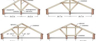
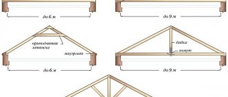
Mansard roof rafter system
Most private houses have a usable under-roof space called an attic. This design is characterized by an increased height of the slope, which is caused by the need to create a living space of a comfortable height. As a rule, the slopes of an attic roof are broken, having a varying slope angle. For their installation, a double rafter system is used.
The steepness of the lower slopes of the attic roof significantly exceeds the slope of their upper extensions. The plane load perceived by them is not large. Thanks to this, the rafters in the lower part can be installed with maximum spacing. It is recommended to install the upper ridge slopes with a reduced gap from each other.
What factors influence the distance between the rafters of a gable roof
There are many different opinions from inexperienced developers about how to choose the distance between the rafters. Some seriously give advice on choosing this parameter for each type of roofing material: natural or artificial piece tiles, metal tiles and corrugated sheets, soft bitumen or slate coverings. In fact, none of this is true; architects never put this in the initial data when calculating the pitch rafter system type of roof.
The physical properties of roofing materials, together with other factors, influence not the distance between the rafters, but their dimensions and additional structural elements of the rafter system to increase the stability of the structure, including:
- vertical supports;
- horizontal purlins;
- corner supports;
- crossbars and other special elements.
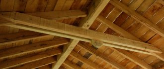
Some elements of the rafter system
The roof structure of a wooden house has many different elements, each of which performs its own function and is fixed in a certain way. To find out in detail what elements the roof of a wooden house consists of, read the article on our website. You will find not only descriptions of the elements, but also the best practical tips!
Before starting calculations, engineers have initial data (technical specifications) for the entire system; taking these values into account, other parameters are calculated. The initial data also includes the pitch of the rafters; it is known before the start of design and does not change in the final project. What exactly affects this parameter?
| Factors affecting the distance between rafters | Short description |
Roof type | This factor has an effect only if it is planned to make the roof insulated. The design specifications must indicate the type and dimensions of insulation used, but they vary. For example, the standard width of polystyrene foam and pressed mineral wool is 60 cm. In order to eliminate the formation of cold bridges, facilitate and speed up the process of installing insulation and minimize the amount of unproductive waste, the span between the rafters should be within 56–58 cm. Rolled mineral wool can have width from 120 cm to 100 cm. Accordingly, their installation requires a different pitch of the rafter legs. |
Economic expediency | The greater the distance, the more load each rafter leg takes. This affects its size and the total amount of lumber for the roof. Currently, wood belongs to a very expensive category of building materials; it is necessary to reduce consumption. This is done both by using additional supports of the rafter system for optimal load distribution, and by adjusting the number of rafter legs, which allows you to reduce the cross-section of the roof elements and save expensive boards. |
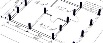
Manufacturability | Each house has its own architectural features. This refers to the location and number of chimneys and ventilation outlets, the layout of the attic space, the materials used to manufacture load-bearing walls, the presence of a wooden mauerlat or concrete reinforcing belt. Rafters cannot be located above chimneys and ventilation pipes, interfere with the installation of skylights, etc. Such nuances must be thought through during the design of the structure; they also affect the distance between the rafters. |
Important. The pitch of the rafter legs is measured between the axes; when choosing the final parameter, you need to take into account the thickness of the boards. For installation of insulation, the distance between the side planes, and not the axes of the rafters, is important.
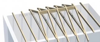
Rafters in a pitched roof
For outbuildings and some private houses, roofs with one slope are used. Due to the limited angle of inclination, high pressure is exerted on them. Experts recommend using lumber with a larger cross-section for the rafters of a pitched roof, setting a minimum spacing from each other.
When calculating the distances at which roof beams are installed, special attention should be paid to the amount of snow load in a particular area. With a small slope, this characteristic is of great importance. It is better to choose roofing material for such roofs with a minimum dead weight, which will reduce the bending load.
What are the calculations based on?
When making calculations, four main indicators are taken into account:
- load per square meter of roof;
- design features of roofing material;
- span length between supports;
- rafter leg mounting angle.
The most important thing is to calculate the maximum roof load, consisting of:
- rafter weights,
- sheathing weight,
- weight of roofing material and insulation,
- snow load (reference information unique to each region),
- wind load (also reference information),
- person’s weight (if repairs or cleaning are necessary, 175 kg/sq.m).
To carry out accurate calculations, experts use special formulas from strength-of-material materials, but when constructing a private one, you can use approximate recommendations.
Hip roof rafter system
The hip roof rafter system is considered the most complex in construction. This type is called hipped, since the roof is formed not only by side, but also by additional end slopes, where the rafters are installed not on the ridge, but on the corner bowstrings. This places special demands on the organization of the roof frame.
An attic is not often installed under a hip roof. This is due to the small angle of inclination of the rafters and the roof as a whole. If the angle of the slopes to the horizon increases, the distance between the rafters increases; if it decreases, vice versa. An additional aspect of the calculation is the roofing material used.
Calculation of strength and deformations
For a rafter as a simply supported beam with a length equal to the span between the supports, the maximum bending moment from a uniformly distributed load is found. Next, the effective stress in the most loaded section is determined. It should be less than the calculated bending resistance for the wood species used.
If this condition is met, the deformations are checked. They should not exceed 1/200 of the span length. In this case, the pitch and cross-section of the rafters satisfies all the specified requirements.
If any condition is not met, you need to reduce the step, increase the cross-section of the beam, or apply both actions at once. You can start from the required distance between the rafters, for example for laying insulation, and use a reverse calculation to find the required geometric parameters of the section.
For warm roofs, the cross-sectional height of the rafter leg must be no less than the thickness of the heat insulator required by thermal engineering calculations for a specific area. In temperate latitudes it is 200 mm (for mineral wool). Even if the calculation requires a smaller sectional height of the rafters, it is not changed. This will avoid installing additional structures to secure the insulation. Mineral wool slabs are simply inserted between the beams, where they are held in place by elastic thrust forces.
Scheme for calculating rafter pitch
According to building codes, the pitch of roof rafters is in the range of 0.6 - 1 meter. Its final calculation is performed using a simple formula depending on the total length of the roof. To calculate, you need to perform the following list of actions:
- determine what distance should be between the rafters for your specific construction conditions. The reference book determines the magnitude of wind and snow loads in the area.
- The length of the roof is divided by the desired distance, adding one. The result obtained will be equal to the number of rafter legs that are installed on one roof slope. If the value is not a whole number, it is rounded.
- The length of the roof is divided by the number of rafters calculated above, we get the final pitch in meters.
For example, with a slope slope of 30 degrees, the maximum distance between the rafters of a gable roof under metal tiles is 0.6 measures. The length is assumed to be 16 meters. Hence:
- 16:0,6+1=27,66;
- rounding the result, we get 28 rafters per slope;
- 16:28 = 0.57 meters - the center distance of the rafter legs for these specific conditions.
As you can see, the calculation technology is not complicated, but this is just an approximate diagram. Taking into account many of the other parameters mentioned above can make certain adjustments.
How to calculate loads
Loads can be permanent or temporary:
- Constants are the own weight of the roof, all its structures, coatings, insulation, etc.
- Temporary - from portable equipment, people, repair materials, snow, wind.
The calculation also takes into account the effect of special loads - seismic, explosive, as a result of fire or natural disasters. Permanent, temporary and special loads can be combined, so they are summarized using combination factors. Loads and impacts, including those associated with climatic phenomena, are determined according to SP 20.13330.2016.
Constant
The load is calculated entirely for the entire roof or for 1 sq.m. The permanent ones include:
- The weight of the roofing, which can be found in the technical description or obtained from the manufacturer. It is indicated in kg/m².
- The weight of the lathing, which for different roofing materials can be in the range of 15-25 kg/m². It depends on whether the flooring will be continuous or sparse.
- Insulation with insulation weighs approximately 10-20 kg/m². If thermal insulation is not provided, then it is not taken into account.
- The weight of the rafter legs themselves. Therefore, their parameters are immediately set, which are determined from the geometric characteristics of the roof and the recommended ratio of cross-section to length.
To find the weight of all the rafters, the density of the wood is multiplied by the volume of one beam, and then by the number of beams. You first need to know the cross-sectional area of one rafter and its length, as well as the species of a particular tree.
Having summed up all the constant loads, it is necessary to adjust the resulting value with an increasing reliability factor of 1.1. Then this value must be divided by the total roof area and multiplied by the cargo area. This is the constant load on 1 rafter.
Snow load
To determine the snow load, you need to find the standard weight of snow cover according to SP 20.13330.2016 for your region. We wrote about how to clear the roof of snow here.
It is indicated for a horizontal surface of the earth. To switch to an oblique projection, you need to take into account the coefficient µ, which is determined depending on the angle of the slope:
- if the slope is less than or equal to 30°, then µ=1;
- at angle values from 30 to 60° µ is in the range from 0 to 1 (determined by interpolation);
- for a steep slope of more than 60° µ=0, i.e. snow load is not taken into account at all.
Schemes of standard snow loads
Next, the snow load is adjusted taking into account the reliability coefficient, which is at least 1.4. An increase of 40% allows for a safety margin in case of extreme snow accumulation.
Wind
The effect of wind on a roof depends on factors:
- shape and height of the building;
- slope angle;
- region;
- the nature of the surrounding buildings.
Wind load according to SP is classified into main, peak, resonant and aerodynamic. When designing private houses, it is possible to simplify rather complex calculations by using the coefficient k, which takes into account the change in wind pressure along the height and the aerodynamic coefficient c, which is taken as a maximum of 0.8.
To determine the standard load, you need to know your wind region, which can be from I to VII.
The standard load, depending on the type of terrain and the height of the structure, is adjusted by the coefficient k, as well as the aerodynamic coefficient c.
The coefficient k can be either decreasing or increasing. In an open field with a house height of more than 10 m, it is maximum and amounts to 1.25, and in dense urban areas for buildings up to 10 m it is minimal - only 0.4.
The aerodynamic coefficient c is determined depending on the slope angle and the direction of the average wind speed. Using the tables in Appendix SP, the value is found for each section of the roof on both the windward and leeward sides. Next, its maximum coefficient value is included in the calculation.
Values of aerodynamic wind load coefficients
After multiplying the standard wind pressure by all coefficients, an increasing reliability factor of 1.4 is used. It increases the design load to provide the required safety margin.
Load Combination
Permanent and temporary loads never act simultaneously. We need to find their most likely combination. As a rule, reduction factors from 0.3 to 0.8 are used.
But in the case of calculating rafters, such conventions can be neglected and the permanent load can be summed up with the temporary load. After multiplying by the cargo area, you can begin to check the correctness of the assigned pitch and section.
Functional rafters: detailed calculation
We come to the main question: what distance should be between the rafters of the roof of a residential building? Here, be patient and carefully study all the nuances.
Point 1. Wall length and choice of rafter spacing
The first step in installing rafters on the roof of a residential building is usually chosen structurally based on the size of the building, although taking into account many other factors.
For example, the easiest way is to install rafters in 1-meter increments, so for a wall 6 meters long, 7 rafters are installed as a standard. At the same time, you can save money by placing them at a distance of 1 and 2 meters, and you will get exactly 5 rafters. It can also be placed at a distance of 2 and 3 meters, but reinforced with lathing. But it is extremely undesirable to make the rafter spacing more than 2 meters.
Point 2. The influence of snow and wind loads on the shape of the roof
So, we settled on the fact that the average distance between the rafters of a regular roof is 1 meter. But, if the area has a significant snow or wind load, or the roof is more or less flat or simply heavy (for example, covered with clay tiles), then this distance must be reduced to 60-80 cm. But on a roof with a slope of more than 45 degrees it can be even increase to a distance of 1.2 m-1.4 m.
Why is this so important? Let's figure it out. The fact is that the air flow collides on its way with the wall under the roof of the building, and turbulence occurs there, after which the wind hits the eaves of the roof. It turns out that the wind flow seems to bend around the slope of the roof, but at the same time trying to lift it. And at this moment forces arise in the roof that are ready to tear it off or overturn it - these are two windward sides and one lifting side.
There is another force that arises from wind pressure and acts perpendicular to the slope, trying to press the roof slope inward. And the greater the angle of inclination of the roof slope, the more important are the safe wind forces and the less tangential ones. And the greater the angle of the slope, the less often you need to install rafters.
This map of the average wind load will help you understand whether to make a high roof or a flat one:
The second point: in the Russian region, the standard roof of a house is constantly exposed to such atmospheric phenomena as snow. Here too, you need to take into account that the snow bag usually accumulates more on one side of the roof than on the other.
That is why in places where such a bag is possible, you need to insert paired rafter legs or make a continuous sheathing. The easiest way to identify such places is by the wind rose: single rafters are placed on the windward side, and paired rafters are placed on the leeward side.
If you are building a house for the first time, then you won’t have to decide on your own worldview, but rather determine the average snow load for your area according to official data:
Point 3. The issue of insulation and standard width of mats
If you will be insulating the roof, then it is advisable to set the pitch of the rafters to the standard sizes of insulation boards, which are 60, 80 cm and 120 cm.
Modern insulation materials are now sold in standard widths, usually at the same standard rafter spacing. If you then take them and adjust them to existing parameters, then there will be a lot of waste, cracks, cold bridges and other problems.
Point 4. Quality and strength of the lumber used
It is also of great importance what kind of material you use to build the rafter system. Thus, for each type of wood there is its own regulatory documentation that concerns its load-bearing capacity:
Because For the manufacture of roof truss systems in Russia, pine and spruce are most often used; their bending strength and features of use have long been prescribed. If you use wood of other species, you can derive a correction factor.
Determining the cross section of rafters
The rafters of roofs of varying steepness perform ambiguous work. The rafters of flat structures are affected mainly by a bending moment; on analogues of steep systems, a compressive force is added to it. Therefore, when calculating the cross-section of rafters, the slope of the slopes must be taken into account.
Only bending stress acts on the rafters of roofs of the specified steepness. They are calculated for the maximum bending moment with the application of all types of load. Moreover, temporary, i.e. climatic loads are used in calculations based on maximum values.
For rafters that have only supports under both of their own edges, the point of maximum bending will be in the very center of the rafter leg. If the rafter is laid on three supports and made up of two simple beams, then the moments of maximum bending will occur in the middle of both spans.
For a solid rafter on three supports, the maximum bend will be in the area of the central support, but since... there is a support under the bending section, then it will be directed upward, and not downward as in the previous cases.
For normal operation of the rafter legs in the system, two rules must be followed:
- The internal stress formed in the rafter during bending as a result of the load applied to it must be less than the calculated value of the bending resistance of the lumber.
- The deflection of the rafter leg must be less than the normalized deflection value, which is determined by the ratio L/200, i.e. the element is allowed to bend only one two-hundredth of its actual length.
Further calculations consist of sequential selection of the dimensions of the rafter leg, which will ultimately satisfy the specified conditions. There are two formulas for calculating the cross section. One of them is used to determine the height of a board or beam based on an arbitrarily specified thickness. The second formula is used to calculate the thickness at an arbitrarily specified height.
It is not necessary to use both formulas in calculations; it is enough to use only one. The result obtained as a result of the calculations is checked against the first and second limit states. If the calculated value is obtained with an impressive margin of safety, the arbitrary indicator entered into the formula can be reduced so as not to overpay for the material.
If the calculated value of the bending moment turns out to be greater than L/200, then the arbitrary value is increased. The selection is carried out in accordance with the standard sizes of commercially available lumber. This is how the cross section is selected until the optimal option is calculated and obtained.
Let's consider a simple example of calculations using the formula b = 6Wh². Suppose h = 15 cm, and W is the ratio M/Rben. We calculate the value of M using the formula g×L2/8, where g is the total load vertically directed on the rafter leg, and L is the span length equal to 4 m.
Rizg for softwood lumber is accepted in accordance with technical standards as 130 kg/cm2. Let's say we calculated the total load in advance, and it turned out to be equal to 345 kg/m. Then:
M = 345 kg/m × 16m2/8 = 690 kg/m
To convert to kg/cm, divide the result by 100, we get 0.690 kg/cm.
W = 0.690 kg/cm/130 kg/cm2 = 0.00531 cm
B = 6 × 0.00531 cm × 152 cm = 7.16 cm
We round the result up as expected and find that to install the rafters, taking into account the load given in the example, you will need a beam of 150x75 mm.
We check the result for both conditions and make sure that the material with the currently calculated cross-section is suitable for us. σ = 0.0036; f = 1.39
Roof rafters with a slope of more than 30º are forced to resist not only bending, but also the force compressing them along their own axis. In this case, in addition to checking the bending resistance described above and the bending value, it is necessary to calculate the rafters based on internal stress.
Those. the actions are performed in a similar order, but there are slightly more verification calculations. In the same way, an arbitrary height or arbitrary thickness of the lumber is set, with its help the second section parameter is calculated, and then a check is carried out for compliance with the above three technical conditions, including compression resistance.
If it is necessary to increase the load-bearing capacity of the rafters, the arbitrary values entered into the formulas are increased. If the safety factor is large enough and the standard deflection significantly exceeds the calculated value, then it makes sense to perform the calculations again, reducing the height or thickness of the material.
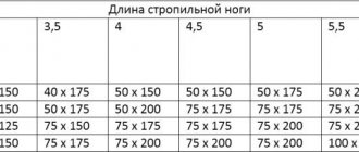
A table that summarizes the generally accepted sizes of lumber produced by us will help you select the initial data for making calculations. It will help you select the cross-section and length of the rafter legs for initial calculations.
Installation of sheathing
How to make a sheathing for corrugated sheets? First of all, you should pay attention to the structure of the roofing pie of a pitched roof, if corrugated sheeting is used as the finishing coating. On top of the rafters it is necessary to lay waterproofing made of roofing felt or a special waterproof membrane
A roof made of corrugated sheets requires high-quality ventilation, so along the rafters, on top of the waterproofing, it is necessary to fill bars with a cross-section of 50×50 mm - the counter-lattice makes it possible to create the required ventilation gap
.
The lathing is attached to the counter-lattice. To do this, boards or bars are packed parallel to the cornice strictly horizontally. To simplify installation, it is recommended to tighten the rope, securing it along the edges of the slope and checking its horizontalness; it is better to use a wooden template.
The lathing is attached to the wooden bars of the counter-lattice with staples or nails; if metal elements are used, self-tapping screws should be used. It is attached to the concrete base of the roof using dowels.
At the bottom of the slope, parallel to the cornice, the main sheathing board is attached; its thickness should be greater than that of the other elements. The thickness of the board is selected based on the height of the profile of the corrugated sheet, as well as the length of the fasteners used, with which the outer side of the roofing sheet is secured.
Wind boards must be installed at the ends of the roof slope. Their surface should be higher than the other elements of the sheathing, at the height of the profile of the corrugated sheet.
Installation of the sheathing under the corrugated sheet is then carried out in the direction from bottom to top. Each beam is attached to each rafter with one nail. To attach the board to each rafter, use two nails along the top and bottom edges to avoid the board from turning inside out and damaging the roofing under high loads.
The sheathing elements should be joined lengthwise on the rafters, securing each end with nails or staples. The sheathing of adjacent tiers should not be joined on one rafter leg.
Principles for calculating lathing under corrugated sheets
Like most roofing coverings, the profiled sheet is attached to the sheathing. The spacing of the sheathing under the corrugated sheet is specified in the building codes. SNiP specifies the requirements for this parameter, based on the angle of inclination of the roof slope
:
- with a minimum roof slope, installation of corrugated sheeting requires a continuous sheathing, or sheathing with a pitch not exceeding 400 mm (the choice depends on the thickness of the metal and the brand of material used);
- with an average slope, the wooden base can be mounted in increments of 300 - 650 mm;
- if the roof has a large slope angle, the pitch can be up to 1000 mm;
- Certain grades of corrugated sheeting with high rigidity can be installed with sheathing pitches of up to 3000 or 4000 mm, if the slope angle is more than 8 degrees.
When designing a roofing system, you should decide in advance on the material of the finishing coating. Manufacturers of corrugated sheets indicate in the accompanying documentation the requirements for laying a specific material. It is recommended to calculate the lathing for corrugated sheeting in accordance with the parameters specified by the manufacturer (they do not exceed the requirements of SNiP).
In private construction, corrugated sheeting with a profile 35 mm high from a steel sheet 0.6-0.7 mm thick is often chosen. Such material can be mounted on the lathing in increments of up to 1.5 meters, while the roof is designed for a load of up to 600 kg per square meter.
You can safely move on such a roof when cleaning or repairing, but it should be noted that this high-strength structure is somewhat more expensive than a roof made of corrugated sheeting of lower rigidity.
If it is intended to use corrugated sheeting with a profile height of 21 mm or less, the pitch of the lathing under the corrugated sheeting should be minimal, or a continuous sheathing should be installed. This roofing material is not designed for high loads; it requires a strong base to avoid deformation of the sheets.
Profiled sheets with a profile height of 44 mm or more are practically not used in private construction, since this material is intended for arranging the roof of industrial buildings
.
Preparing material for lathing
To calculate the amount of lumber required, you need to know the length and width of the slope, as well as calculate the pitch. In addition, it should be taken into account that two boards should be installed at the ridge and eaves to ensure the necessary strength of the roofing deck.
Reinforcements are also required at the junction of chimneys, dormer windows, ventilation ducts, etc. Another 10% should be added to the calculation result. since during the installation process the lumber will have to be cut to the required size and some will go to waste.
The cross-section of the bar must be at least 50×50 mm. The sheathing can also be made from edged or unedged boards 50 mm thick. It is necessary to use well-dried lumber. It is recommended to use beams and boards made of spruce, pine, beech, and alder
The material may not be jointed, but you should pay attention to the straightness of its surfaces
Boards and beams should not be warped; if necessary, the surface of the elements should be corrected.
The lathing under corrugated sheeting is used in conditions of high humidity, so there is a high risk of damage to wooden elements by fungus and microorganisms. To prevent wood rotting, lumber must be treated with antiseptics. Fire protection treatment of roof elements is also necessary. Today, special compositions for fire-bioprotection are produced that allow both types of treatment to be carried out at one time.
It is possible to process ready-made sheathing, but the roof structure will be protected much more effectively if it is assembled from elements that have been pre-impregnated with a high-quality fire-retardant composition.
Calculation of material quantity
The number of beams depends on the total roof area and the installation pitch
The length of the roof overhang is divided by the approximate pitch of the rafters. The result obtained is rounded upward and one is added. This is how the number of rafters is obtained. To find out the exact distance between the elements, divide the length of the cornice by the number of rafters.
Calculation example:
- overhang length 27 m, approximate gap 0.8 m;
- calculating the number of rafters: 27 / 0.8, you get 33.75 (34) pieces, add 1, you get the number of 35 pieces;
- exact interval: 27 / 35 = 0.77 m.
The number of battens is determined by dividing the length of the ramp by the step distance. The total length of the boards or slats is calculated by multiplying their number by the length of the overhang. Take into account that in difficult junction areas, ridge areas, and on the eaves, double sheathing is installed.