Construction using the pile method is an economical and reliable method. When using it, take into account:
- distance between screw piles for a frame house;
Drawing with dimensions of the distances between piles at the base of the building
- pile placement procedure;
- distance between posts in a frame house;
- ways to deepen supports.
You can calculate the distance between the posts of a frame house yourself. Based on this, draw up an estimate and a list of materials.
Soil features on the site
The strength and reliability of contact between the shaft and blades of each pile and the adjacent layers largely depends on the soil parameters. According to the requirements of SNiP, for soil analysis it is necessary to carry out test drilling and laboratory studies of the composition and properties of soil layers.
In addition, it is recommended to install reference piles that can demonstrate in practice the load-bearing capacity of the pile and the amount of load resistance. In practice, most studies are limited to test drilling and visual determination of soil quality.
The depth of dense layers and their composition are determined by the soil resistance during drilling.
NOTE!
An experienced driller is able to assess the condition of the soil no worse than a specialist geologist, however, if it is possible to perform a high-quality soil analysis, it should not be neglected.
Load calculation
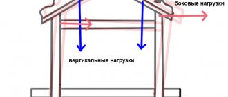
The load on the base is the total value added from the following values:
- The weight of the house with all structures, floors and other structural elements.
- The amount of snow load on the roof in winter.
- Wind load.
- Operating load.
The weight of a house is a calculated value that is obtained by adding the weight of the walls, roof, ceilings and other elements. All necessary data can be taken from SNiP applications, multiplying specific values by the area or volume of existing structures.
This stage of calculations is the longest; it is important not to miss any structures and to take into account all the elements. It is necessary to exercise maximum care and consistently add the weight of all parts of the house.
The snow load is determined by multiplying the total roof area by the specific snow pressure (per m2) . This value is available in SNiP applications, the appropriate region is selected and the necessary data is obtained.
The same method is used to determine wind load, a very relevant parameter for some regions.
Operating load is the weight of people, furniture, household appliances and other property located in the house. These values should not be neglected, since they significantly change the overall magnitude of the loads.
IMPORTANT!
The total calculated amount of loads should be increased by 10-15% in order to have some margin of bearing capacity of the base. This can compensate for possible additional load from the weight of the skin or other elements not previously taken into account.
Preparation for production
At the preparatory stage, it is necessary to find out the dimensions of the future structure, the load on the foundation of higher structures and the bearing capacity of the soil. Before building a frame house, you can do a soil test yourself. To do this, you need to drill several holes in the area. The depth of the well is below 50 cm of the base of the foundation. In this way, the type of soil and the absence of aquifers are determined.
Soil characteristics:
- Rocky - soils with a high content of stone or gravel, have a strong foundation, hold the load well, and do not collect water.
- Coarse sands are a strong base with low heaving.
- Fine sand - not suitable for construction, as they are characterized by high heaving. They collect water in the upper layers and act as a buoyant force on the foundation.
Calculations of depth and number of pillars
Columnar foundations can be buried (for water-saturated and clay soils) and shallow (for rocky and sandy soils with low groundwater levels). The height of the buried foundation depends on the average depth of soil freezing in your area. The base of such a foundation should be located 30–50 cm below this level. Before starting work, you should calculate the load of the house; for this, the weight of the walls, ceilings, roof and the weight of the foundation are summed up.
| Construction type | weight |
| Frame insulated walls 15o mm thick | 25–50 kg/m² |
| Wooden beams with ceilings and insulation | 90–140 kg/m² |
| Roof and snow load | |
| Metal | 45–60 kg/m² |
| From flexible tiles | 45–65 kg/m² |
| Ceramic | 75–115 kg/m² |
| Snow load in different regions of Russia | |
| Middle lane | 100 kg/m² |
| Southern regions | 50 kg/m² |
| Northern part of the country | 90 kg/m² |
To determine the weight of a reinforced concrete columnar foundation, its volume must be multiplied by the specific weight of reinforced concrete (2500 kg/m³). To calculate the weight of one column, the following formula is used: V=3.14*G²*h. V is the volume of the column, G is the radius of the column, h is the height of the column. All values are indicated in meters. The resulting value must be multiplied by the number of pillars, and we will get the total volume of the foundation.
Bearing capacity of different soils (in kg/cm²):
| Soil bearing capacity | |
| Pebbles with clay | 4,5 |
| Coarse sand | 6 |
| Medium sandy | 5 |
| Fine sand | 4 |
| Gravel with clay | 4 |
| Loam | 3.5 |
| Clay | 5 |
Material selection and quantity calculation
Different materials are used to construct a columnar foundation:
- Wood is a very short-lived material; even when treated with protective compounds, it will last no more than 20 years.
- Stone pillars - usually constructed from rubble or granite stones. They are distinguished by durability and reliability. The disadvantage is that it is massive and labor-intensive to build.
- Monolithic concrete pillars.
In order to calculate the amount of concrete for a columnar foundation, you can use the following table:
| Radius of a pillar with a circular cross-section | |
| 7.5 cm | 0.0176 m³ |
| 10 cm | 0.0314 m³ |
| 15 cm | 0.07 m³ |
| Square section | |
| 20x20 cm | 0.04 m³ |
| 30x30 cm | 0.09 m³ |
| 40x40 cm | 0.16 m³ |
The reinforcement for the columnar base is corrugated, class A, with a diameter of 10–12 mm. Metal rods are needed the same length as the supports. For a post with a diameter of 10–14 mm you will need 4 bars of reinforcement. They are placed at a distance of 10 cm from each other and tied every half meter with smooth and thinner reinforcement with a diameter of 6 mm. Thus, for a two-meter pole you will need 8 m of thick and 1.2 m of thin reinforcement. We multiply the resulting figures by the number of supports and obtain the footage of the reinforcement required for the columnar base.
Required Tools
Before starting construction, you need to prepare the following tools:
- Concrete mixer;
- Shovel;
- Roulette;
- Level;
- Nails and screws;
- Hammer;
- Cord;
- Pegs;
- Hand drill;
- Master OK;
- Pipes or boards for formwork.
Basic placement schemes on the foundation
There are various pile placement schemes:
- Singles.
- Dolphin.
- Pile field.
- Pile tape.
The choice of scheme is determined by the configuration of the building and the order of load distribution. Individual piles are used to create point supports for pillars or other elements of a minimum area.
Pile bushes are used for high loads, not just one, which happens during the construction of multi-story buildings, large hangars, etc. The pile field is used for heavy buildings with uniform load distribution over the entire base area.
Installation of supports is carried out either in longitudinal-transverse rows, or in a checkerboard pattern . Tapes are necessary when creating structures that have an extended structure with a small width (embankments, retaining walls, fences, etc.).
It must be taken into account that the design configuration of the pile field does not always fully comply with the requirements of SNiP. Situations often arise when the number of supports does not correspond to the load due to the placement features.
In such cases, it is necessary to increase the number of piles or slightly adjust the configuration of the pile field taking into account the specific loads.
How to calculate the distance correctly
There are many different methods for calculating screw piles. Most of them are incorrect and do not provide any useful results . A competent calculation can be made, guided by SP 50-102-2003, which sets out all the necessary formulas and methods.
The problem is that there are no simple methods; you will have to make quite complex calculations with a high probability of error. Therefore, it is necessary to contact specialists or, at a minimum, use online calculators that allow you to get the required values in just a couple of minutes and completely free of charge.
NOTE!
It is strongly not recommended to undertake foundation calculations on your own without appropriate training and experience due to the high probability of errors and incorrect use of various special values.
If you still need to calculate the pitch of the supports, you should first draw a plan of the pile field (or use the plan of the first floor) . First, the piles are placed at all corners and junction points of the walls.
After this, piles are distributed along the load placement lines (load-bearing walls) based on their number.
Sometimes, when the weight is evenly distributed over all supports, they do it simply - calculate the total length of the load-bearing walls and divide it by the estimated number of piles.
For example:
The weight of the house is 300 tons. The nominal load on the pile is 5 tons (VS-108).
Total number of piles:
300: 5 = 60 pcs.
The total length of the reference lines is 40 m.
Then the distance between adjacent piles will be:
60: 40 = 1.5 m.
Working with piles
When all the supports are screwed in, make a grillage. The first step is leveling the height and filling with concrete. For this, the following can be used: board, timber, metal corner, beam.
The process of leveling the pile in height
Regardless of which material was chosen, it must be processed to extend its service life.
According to the area of the building, the formwork is made wider than the load-bearing walls.
Formwork design for pouring the foundation grillage
A frame is mounted in it, which is secured using spacers. Then it is filled with concrete. After the concrete has hardened (this will take about a month), the formwork boards are removed. Concrete is treated with mastic for waterproofing.
We suggest you familiarize yourself with which nails are better: screw or ruff nails
A layer of roofing material, also treated with mastic, is laid on top of it. After it has completely dried, you can begin building the walls.
The process of treating a pile foundation with mastic
Construction using the pile-screw method is easy to do. You can build a bathhouse or a house on your summer cottage yourself. The independence of construction from the season or terrain features is another plus of construction in this way.
After installation of screw piles, additional work is carried out. First of all, you should make sure that all supports are installed level. There should be at least 60 cm from the ground to the zero level of the house. We align all the piles so that they are in the same plane. For this you can use a grinder.
Next, the supports are concreted to give them strength. This will eliminate the possibility of tilting and deformation of the future foundation. It is also necessary to expel air from the cavities so that the foundation does not collapse in the future.
The mixture is poured into the internal void of the pile, it is also necessary to lay reinforcement, this will give the structure reliability. For this, a cement-sand mixture is prepared. Its consumption is 35 kg per 1 pile.
The final stage of mounting the supports is to weld the ends. After this, timber tying is performed. If you use a channel instead of a beam, then you can do without the heads. This will help you save a lot.
Working with a pile-screw foundation excludes the following actions:
- Adjusting the piles to the same level during screwing. This work is carried out after the installation of all supports is completed, otherwise it may provoke subsidence of the foundation in the future;
- Lengthening unevenly screwed in piles;
- Installation of supports less than 1.5 m into the ground;
- Creating preparatory holes for supports in the ground deeper than 50 cm;
Minimum and maximum value between supports
According to SNiP requirements, the minimum distance between two adjacent screw piles is double the diameter of the blades. That is, if there are supports with 30 cm blades, the minimum distance between them will be 60 cm.
It is necessary to take into account that this is the distance between the blades, that is, when marking, marking the axes of the piles, one should consider not 2, but 3 diameters. The maximum distance is determined by the ratio of the weight of the house to the number of piles.
It is necessary to take into account the material and cross-section of the grillage so as not to cause excessive movement of the beams in the central part of each span . According to all calculations, the maximum is always determined as 3, in some cases - 3.5 m.
It is impossible to go beyond these values, this will create a threat to the structures of the house.
Type of piles
The supports are distinguished by the method of deepening into the ground:
- Screw - a pipe with a diameter of 70 - 350 mm and a length of 2 - 11 m with a screw cone-shaped end;
Foundation design on screw piles - Driven ones - length up to 16 meters; to increase the length, joining of several pieces is possible;
- Drilling rigs are installed in a drilled well.
According to the material:
- Reinforced concrete – concrete reinforcement;
- Steel – grade not lower than ST-3;
- Tree.
Wooden ones are made from larch or oak.
Optimal value
It is very difficult to clearly indicate the optimal distance between adjacent piles of a screw foundation. It is necessary to take into account a lot of specific factors specific only to a given site, building and other conditions of construction and operation.
However, there are certain limits that limit the minimum and maximum pitch between screw supports. Logically, the optimal distance should be the average value, but in reality the situation looks somewhat different.
Based on the results of experiments and practical tests, it was found that the optimal distance is 2 m . This value is suitable for almost all types and sizes of piles used in individual construction.
The optimal value should not be used as some kind of universal number that is suitable in any case. Each project must be calculated individually.