Pile foundations are perfect for problematic soils. It is very important to place the supports correctly so that the foundation of the building is strong enough. Particular attention is paid to the distance between piles.
The necessary calculations are made at the design stage. If the piles are placed too far away, the building will sag. If it is too close, financial costs will increase. The maximum permissible load is calculated taking into account the characteristics of the soil on the site and the type of structure being built.
Before construction begins, a soil analysis must be performed. Knowledge about its structure and variety will allow you to determine the required number of piles, select their optimal sizes and diameters, and the required depth of twisting. The data obtained allows us to determine the appropriate type of foundation.
To conduct a soil analysis, test drilling is performed. Then the soil is collected and tested in the laboratory. If the soil strength is high, then the pile is buried by 2.5 meters, low - by 4 meters. The bearing capacity of the soil must be taken into account, as it allows one to calculate the permissible load on the piles. This load consists of:
- Weight of the building taking into account decoration and furniture;
- Snow load;
- Operating load;
- Wind load.
Snow load depends on the specific region. The snow load indicator is calculated using the formula: weight of snow flooring = layer of snow per 1 sq.m. x S roof surface.
The operational load depends on the type of structure being built and is determined in accordance with current state standards. For industrial facilities it is 200 kg/sq.m., for residential buildings - 150 kg/sq.m. The higher the load, the smaller the distance between the piles and the more supports will be needed.
How is a pile foundation constructed?
A pile structure can be represented as a set of load-bearing elements and a grillage. Support elements may differ in material and installation method. For example, today it is practiced to use driven and screw piles. To determine the distance between piles in a pile foundation, it is necessary to take into account the permissible burial depth, material of manufacture and other parameters of load-bearing products - this is how the number of elements and the step between them is calculated.
No less significant is the function of the grillage, which provides a bunch of free-standing supports. It can be implemented in different types and designs, but, as a rule, the design of this component depends entirely on the technology for introducing and strengthening the piles. Engineers usually focus on taking into account the properties of the soil and the expected mass of the future structure - together, this information makes it possible to lay the optimal pile-screw foundation . The distance between the piles can be calculated based on their number.
To determine how many supporting elements are required, you should know the level of load and the overall load-bearing capacity of the structure. In particular, a pile can withstand about 2 tons, while the weight of the house structure can be tens of tons. Next comes the layout of the placement of piles throughout the entire area. In some cases, the load is uneven, and therefore the location of the piles is not always correct from a geometric point of view.
Construction practice in Russian conditions has established the minimum distance when laying a pile-screw foundation: it is 1.7 m on normal soil. In this case, in each pair a gap (at least 0.5 m) of a solid layer of soil should be left, that is, an area where no excavation work has been carried out. This measure will prevent the undesirable influence of the soil base on the pile foundation.
The maximum distance between piles for one-story buildings is:
- for houses made of logs or timber - 3 m; for frame and prefabricated panel buildings - 3 m; for buildings made of tongue-and-groove blocks, aerated concrete and cinder block - 2.5 m; for brick buildings - 2 m.
As you can see, lightweight wooden buildings require a less dense arrangement of piles, however, if a 2-story building is planned, the step can be reduced.
Load
For a frame house, the greatest distance between the supports cannot exceed 7 steps, since a distance of 8 steps or more is usually used when building large-scale objects, in which, as a rule, a pile network is used.
The minimum distance between supports is the permissible gap between the piles, at which the foundation will not experience shifts and collapse.
We will calculate the exact loads of the building on the foundation and soil mass.
It is important!
A properly laid foundation can withstand several hundred tons, however, if the pitch of bored piles in a strip grillage according to SNiP is calculated incorrectly or inaccurately, this can lead to the destruction of the entire facility, since it will require repairing supporting structures and making changes to the distance between piles.
Let us indicate the density in g/cm3 of some types of soil:
- clay: 2.75;
- sandy loam: 2, 72;
- sands: 2.6-2.7;
- loams: about 3.
Despite the reliable characteristics of the density of all types of soils, calculation of the soil mass is also necessary. However, the standard is the specific gravity of the soil; thanks to this parameter, you can find out the mass of any layer. Not taking into account the density of the soil in different places of the site is tantamount to allowing the foundation to “slide” to the side.
- Dispersed soil: 1.5-2.5 g/cm3.
- Metaphorical soil: about 3 g/cm3.
- Argillite and siltstone: 2-2.5 g/cm3.
- Sandstone: 2-2.7 g/cm3.
- Limestones: 2.2-3 g/cm3.
Calculation of bored piles
Technology for constructing bored piles
Reinforced frames for bored piles
Deviations from the “norm”
Despite the development of uniform rules on the basis of which a method for calculating the distance between piles is drawn up, each case involves a huge number of nuances. In this regard, engineers are beginning to be guided by a simple rule: to designate the maximum limit of the permissible number of piles and rationally distribute them over the entire area, taking into account the loads.
Depending on the project for which a pile foundation is planned, the distance between piles may be reduced or increased.
For example, if the plan provides for an internal load-bearing wall with floor loading on the sides, then it makes sense to reduce the step between load-bearing elements by 30%. Increasing the distance is also not a gross mistake if technical precautions are taken into account. In such cases, additional installation of foundation foundations is usually required beams It is difficult to say what can justify increasing the distance, since such a correction is unlikely to make the pile-grillage foundation more reliable. The distance between the piles, which increases due to savings, also does not justify itself. If only for the reason that additional strengthening will cost more than an “extra” but structurally sound row of foundation piles.
Calculation features
The optimal pitch between piles is calculated at the design stage. The technical parameters, strength and durability of the foundation depend on this value. Maintaining the correct spacing avoids building subsidence if supports are located too far apart and additional costs if they are placed too close together.
When calculating the distance between supports, the specifics of the soil and the weight of the structure are taken into account. It is important that all structural elements rest evenly on the weight distribution points in the foundation - pile supports.
The payload of piles is determined by SNiPs or specifications. On average, one support can support up to 2 tons of weight. However, each case is individual, and for all types of development it is necessary to perform a separate calculation taking into account the type of structure and soil characteristics.
Soil analysis
The construction of any structure begins with a study of the soil on the site planned for development. Conducting a soil analysis will allow you to establish its type and structure, reduce construction risks and determine the depth of piles. Also, based on the data obtained, the type of foundation is selected.
In accordance with building rules and regulations, the following is performed for soil analysis:
- test drilling;
- sampling and laboratory studies of the composition of soil and ground layers.
An experienced specialist is able to determine the condition of the soil visually. However, to obtain reliable data on the bearing capacity of the soil, an accurate study is necessary.
It is enough to carry out test drilling to a depth of 2 m. If the strength of the soil layer is high at 0.5 m, the piles are placed at 2.5 meters. If it is low, it is necessary to go deep to 4 meters.
The bearing capacity of the soil is an important indicator that must be taken into account when calculating the distance of piles. Knowing this soil indicator, you can calculate how much load one support can withstand.
Analysis of building weight and structure
The features of the future building are one of the key parameters that should be taken into account when calculating the distance between supports. The total weight of the load on the foundation consists of the following quantities:
- weight of the house - the estimated weight of the structure, taking into account finishing materials and furniture;
- estimated maximum weight of the snow deck in winter;
- wind load;
- operational load.
The weight of the snow deck depends on the region in which the construction is planned. For each area, it is determined by the standard, as well as the wind load indicator. The snow load indicator is calculated using the formula: weight of snow flooring = layer of snow per 1 sq.m. x S roof surface.
The operational load depends on the type of structure and is determined by GOST. For industrial facilities it is 200 kg/sq.m., for residential buildings - 150 kg/sq.m. An increase in operational load requires the use of more piles when laying the foundation and reducing the distance between them.
Selection of piles
The choice of piles is determined by the structure design, soil type and load factor.
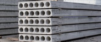
Depending on the material from which the piles are made, wooden, concrete or reinforced concrete and metal supports are distinguished.
- Wooden piles are used very rarely due to their fragility and relatively low load-bearing capacity. More often, concrete or metal piles are used in construction;
- reinforced concrete piles are used in construction more due to their strength and ability to withstand high loads;
- metal supports are made from steel pipes of different diameters and are able to withstand more intense loads compared to wooden options. They are used in construction in areas with difficult to drive soil. The most common type of metal supports is a screw pile, used in various types of soil for the construction of residential buildings, frame houses, and country houses.
The characteristics of the foundations play a significant role in the formation of the bearing capacity of the foundation. The average length of piles presented on the construction market varies from 0.5 to 11.5 m. An important parameter is the diameter of the supports - from 57 mm and above. The larger the diameter of the base, the higher its load-bearing capacity. For example, with a diameter of 76 mm, the pile can withstand a load of 3 tons, while with a diameter of 108 mm, the load-bearing capacity increases to 5-7 tons.
Pile location configuration
In addition to the distance between the piles, the method of their organization is also important. The choice of a specific configuration depends on the existing loads. There are several options for arranging supports on the foundation site: individually, in a row, in the form of various geometric shapes and in the form of a continuous field on which a pile foundation is formed.
The distance between piles in each case is guided by the general rules of calculation, but can be adjusted. The most common are pile strips (row configuration), solid piles and “cluster” dense methods of arranging load-bearing structures. The technique of installing elements in a row is used to support the walls of buildings - this is a common method of constructing a foundation for residential buildings. For structures that involve intense loads, the pile “bush” method is recommended. The continuous field structure is designed to support the heaviest buildings and structures.
In this case, the piles are distributed evenly and are united by a monolithic grillage with a strong base. How to calculate the distance between the piles? This question worries both builders who are responsible for the quality of their work and customers purchasing piles. Moreover, the former want to dot the area with a dense palisade of supports, and the latter demand a report on each pile used. As a result, both are wrong. After all, the distance between the piles is not determined by the opinion of the foreman or the desire of the customer.
This value is included in the project by the architect, who determines the minimum distance based on complex calculations that take into account the weight of the constructed structure, the depth of soil freezing, the load-bearing capacity of the pile, and even the type of support. And in this article we will introduce our readers to the basics of such calculations. ↑Where does the calculation begin? Of course, with determining the bearing capacity of the soil. After all, it is the soil that supports the entire weight of the structure.
Consequently, the less stability of the soil, the more supports are needed and the smaller the distance between the supports. The bearing capacity of the soil is determined in two ways - by analyzing a soil sample and analyzing the bearing capacity of a control pile. Both options are practiced only in the process of geotechnical research. This data cannot be obtained under domestic conditions. Although the bearing capacity of the soil can be determined by its type from special tables. The next step is to determine the total weight of the structure.
After all, the main factor determining the load on one pile is the totality of the masses of building materials, furniture and even snow cover on the roof of the building. Having determined the total weight of the structure and knowing the bearing capacity of the soil, you can calculate the area of the foundation base. For these purposes, use the formula: S = M/N Where S is the area of the sole (in cm2); M is the mass of the structure (in kilograms), N is the load-bearing capacity of the soil (in kg/cm2). As a result, knowing the total area of the base, you can calculate the number of bored piles or screw supports, or driving rods, or any other vertical elements of the pile foundation. For example, if the weight of the house is close to 150 tons, and the load-bearing capacity of the soil is 15 kg/cm2, then the total area of the base will be 10,000 cm2 (150,000 /15). Next, you should select the type of support and calculate the number of piles based on the area of the lower part. So, for a 40-centimeter cylindrical-type bored support, the area of the bottom end is 1256 cm2, and for a classic BC108 screw pore with a blade diameter of 30 centimeters, the bottom area is 706 cm2.
Well, the TISE support with a half-meter expansion in the lower part has a 1960-centimeter base area. Thus, the 150-ton weight of the structure will be supported by 15 BC108 supports (10000/706) or 8 bored supports with a base diameter of 40 centimeters (10000/1256), or 5 TISE supports with a bottom part of 0.5 meters in diameter (10000/1960). ↑Further calculations to determine the distance between the piles look even simpler. After all, the value we are interested in must be between two extreme values - the minimum and maximum possible distance between piles. Simply put: piles cannot be mounted closer than the minimum distance between supports (placement step) and it is inappropriate to immerse further than the maximum distance between supports. And to understand the essence of determining the “pitch” of piles, we must understand the definition of the minimum and maximum values of this parameter. Minimum distance between piles The smallest distance between piles is determined by the thickness of the compaction in the soil that appeared as a result of the installation of the support.
Simply put, when driving a pile or drilling a shaft or screwing a support into the ground, the space around the plunge point is compacted. Therefore, all piles are mounted in increments equal to at least three support diameters. That is, the minimum distance (step) between supports is equal to three pile diameters. And it is not recommended to install piles closer than this distance. Although there are exceptions to the rule.
For example, inclined piles are mounted in increments of one and a half diameters of the support. Maximum distance between piles The largest distance between beams is determined by the load-bearing capacity of the grillage. After all, the slab or beam of the horizontal part of the foundation should not bend under load beyond a certain level. However, builders do not need to remember the formulas for calculating beams from the strength of materials course. It is enough that, according to the generally accepted classification, the maximum step is defined as a distance of 5-6 support diameters. As a result, the distance between the BC108 supports should not be less than 1 meter and cannot be more than 2 meters.
Bored foundations on 40-centimeter supports require a different step - 1.2 meters at a minimum and 2.4 meters at a maximum. In a building construction project, the distance between bored piles is the result of a calculation taking into account all local conditions. In this case, the contractor and the customer comply with the requirements of the relevant section of the design documentation completed by specialists. Indicators for calculations are standardized by construction collections based on the results of analysis of data obtained during engineering and geological studies of the building site.
Acceptable values
According to existing standards, a smaller distance between piles for a frame
object is set equal to 3d. The letter d indicates the diameter of the pile used. For example, with wooden piles it is required to adhere to a certain size of 70 cm, for reinforced concrete piles this value is 90 cm. This requirement is mandatory, otherwise the level of reliability of the foundation, and therefore the structure, is reduced.
Advice:
it is necessary to take into account that if the piles are driven at a certain angle, then a reduction in distance is necessary. Screw pile pitch
should be equal to 1.5d. The main thing is to carefully calculate all the values in advance. If there is a strong slope on the perimeter of the site, supports should be installed frequently to increase the level of reliability of the foundation.
Maximum distance between piles
limited to certain requirements.
Experts believe that in some cases, piles are installed so that the gap between them is 5d or 6d. The applicable distance between piles
is 8d. This requires the presence of the most reliable soil and a small load on the foundation itself and the soil. In addition, the operation of the facility should also be small.
Distance between piles for frame
object installed on sandy soil, the value 4d is applied. This is explained by the fact that when using a minimum gap, the soil may become compacted, which will significantly complicate subsequent installation work.
To perform a correct calculation, it is necessary to determine the thickness of soil compaction, which manifests itself during the construction of the foundation. This will eliminate the possibility of spatial compaction occurring during pile installation. Therefore, a minimum step has been established, which is equal to three times the diametrical value of the support column. A shorter distance is not provided. But there are exceptions, for example, installation of inclined piles, in this case the gap is halved.
Influence of the site on the foundation parameters
Features when designing a foundation using piles are given in SNiP 2.02.03-85:
The length is selected in such a way that the load falls on a strong layer, cutting through weaker layers; On subsidence soils, research for design is carried out only by specialized organizations; Bored pile Based on the complexity of the site, control wells are drilled in increments of no more than 50 meters. For each contour of a separate building, at least 4 drillings are required.
3 wells are allowed for a building base area of up to 1300 m². Based on the results of studying the hydrogeological regime (groundwater), a forecast is made of its likely change during the construction of the designed structure. All soil characteristics that may change during soaking are taken into account based on complete water saturation; In swelling soils, installation can be carried out either with or without complete cutting through the swelling layer. In the case of complete penetration with support on non-swelling layers, compliance with SNiP 2.02.01-83, the lifting of individual components of the foundation is practically excluded; SNiP 2.01.09-91 is additionally taken into account when construction is carried out on undermined areas; The use of SNiP II-7-81 is mandatory * in seismic areas.
Conducting geotechnical surveys can be significantly reduced if the developer has experience in construction on this site and has previously conducted research.
Placement of screw piles in plan
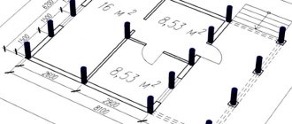
Correctly placed supports will help maintain the integrity of the house. With their help, the load will be evenly distributed under the building area, and therefore unwanted subsidence will be avoided. A house with complex contours in plan requires special attention, especially the corners and junctions of the walls. Installation of screw piles under them is mandatory.
Pile placement patterns depend on the design features of the house. There are four types of their arrangement in plan:
- single - under the vertical posts of a frame house, at corner points, under load-bearing walls (equidistantly in increments of no more than 3 meters);
- strip - under load-bearing walls, but, unlike single screw piles, with a shortened pitch, often reaching up to 0.5 m. The arrangement of supports in the form of a tape allows the foundation to accept and distribute more significant loads;
- cluster - under heavy single or group structures, as well as under massive equipment. The step, in this case, does not matter, since the screw piles at the installation site can be placed too close in a chaotic manner. The main condition is that they must be present along the entire perimeter and area of a small-sized slab grillage required for installation, for example, of a heavy load-bearing column of a frame building;
- continuous, called a pile field. The supports fill the entire area under the foundation slab in increments of about one meter. This placement of screw piles in plan is practiced when designing heavily loaded objects or when building on soils with too weak bearing capacity.
For private houses and small buildings, as a rule, the first two types of screw pile arrangement are used.
Main indicators for calculation
For bored piles, the number, dimensions, and clear distance between them are selected based on the following conditions:
- Soil properties; Total weight of the structure, including the supports themselves; Presence of basements and basements in the project; Forecast of changes in operating conditions (possibility of flooding, underwork, man-made and vibration impacts of neighboring objects); Climatic zone (plus temperatures or deep freezing).
Standards for deepening bored piles
Based on research results, indicators for soils and rocks, climate zoning are taken from tables. The specific gravity of building materials, to determine the total indicator, is indicated in reference books.
If the typical indicators match, you can use pivot tables.
The load-bearing capacity of one support is determined by the soil resistance and the diameter of the column. The calculated value is often lower than the actual value obtained as a result of testing. This is explained by the use of averaged tabular values of quantities.
At a depth of up to 3 m, it is recommended to choose a section of a concrete rod with a diameter of 30 cm (clause 15.2., SP 24.13330.2011; SNiP 2.02.03-85; clause 1810.3.5.2.2, International Building Code IBC -2009). Column base protrudes 100 mm. Example: for a 300 mm post, the base is Ø 500 mm.
How long does it take to drill?
Let's calculate the minimum number of load distribution points on a base with a load-bearing capacity of 4.5 kg/cm².
Let us take the weight of the building, including the entire foundation, to be 140,000 kg. For a 40 cm column, the base will be 60 cm. Therefore, the area of the lower part of one element is 2826 cm².
To distribute all the weight you will need (140000 : 2826)/4.5 = 11.0089. There are 11 drilled rods in total. For comparison, one such support Ø 40 cm made of grade 100 concrete can withstand 40 tons (100 kg/cm²).
It is important not to confuse the load-bearing capacity of a concrete product with the same capacity of the site.
Load distribution
Installation of piles
Each post individually can sag or be squeezed out by swelling when the soil freezes. In this case, a redistribution of the load will occur, violating the stability of the building.
The solution to the problem combines individual pillars in a single bundle - a grillage, which ties all the elements with tape or a plate. To do this, the edges of the reinforcing frame are protruded from the top of the concrete cylinders. The constructive solution must take into account the number of support points, the clear distance between them, and the location of load-bearing walls.
The materials used are poured or prefabricated reinforced concrete, steel profiles, and wooden beams. They design based on the chosen design of the future home. A steel profile is not the best choice - the metal is exposed to aggressive environmental influences, and therefore requires constant maintenance of a protective coating.
The solution that has the most advantages is monolithic filling. The typesetting version will require a lifting mechanism. And his mobility is higher.
How to count a step
The greatest distance between bored supports is determined as the ratio of the load-bearing capacity of the pile (P) to the load of the building per one linear meter of the foundation (Q). In turn, P is the total indicator of the lateral surface and base.
Rosn = 0.7 * Rn * F,
where Rн is the standard bearing capacity, F is the base area of the bored pile, and 0.7 is the coefficient of soil uniformity.
Rbok. surface = 0.8 * U * fiн * h,
where 0.8 is the operating conditions coefficient, U is the cross-sectional perimeter of the pile, fin is the standard soil resistance at the side surface of the pile, h is the height of the soil layer in contact with the foundation.
Location of bored piles
Dividing the mass of the building by its perimeter, we get Q, for example, 6.2 t/m.
The length of the base of not only external, but also internal walls under load (if any) is added to the size. We will first select a pile Ø 30 and 3 m long. P = 12.31 t.
The maximum distance will be 1.98 m.
Now we begin to link the gap between the supports to the geometry of the designed building.
It is necessary to take into account the multiple of the sides of the perimeter and the distance between the pillars. You can increase the size of the clearance by adopting a design part with a larger diameter or length (increase the numerical value of Rosn, Rside. surface).
As the distance between the supports increases, the cross-section of the grillage increases. More concrete and reinforcement are required. It is recommended to calculate several options for the optimal consumption of building materials and the estimated cost of construction.
Construction rules recommend maintaining a distance between drilled columns from 3 to 6 of their diameters. That is, in the light the minimum gap is 2 diameters. Reduction is possible, but not rational.
When drilling, there is no such compression of the soil as when driving. However, the close location of the pillars (less than 1 m) distributes the load on the surface of the base with mutual overlap of base deformation zones. We get the bush principle.
When calculating friction along the lateral surface in a cluster, only the outer conditional perimeter of the entire cluster of support rods is taken into account, which reduces the overall value of this indicator. The deformation stress under the sole also increases, which can increase settlement. Mutual influence in the bush is calculated according to SP 50-102-2003 (clause 7.4.4).
Features of self-construction
Constructing a foundation from bored components is not difficult when building with your own hands.
A hand drill of the required diameter will be used to drill a hole 2 - 3 meters deep. The bored base can be obtained with a cross-section from 15 to 40 cm. TISE technology makes it possible to use a special foundation drill to obtain a well Ø 20 cm with a widening at the bottom of 40 cm; 60 cm, it is possible to use such drills on drive mechanisms.
To confidently penetrate into the solid layer of underlying rocks, the well is drilled below the freezing level, where the layers are compacted. For medium, dry soils the bearing capacity is 6 kg/cm². Watch the video on how to calculate the distance between the piles and place them.
A significant advantage of making reinforced concrete components during construction alone is the ability to prepare small volumes of concrete for each pour. Other types of foundation devices require a much larger amount of ready-made solution at a time.
The need for materials to obtain products with specified properties is visible from the table:
Material requirement table
Unstressed methods
Impact-free methods are based on achieving soil softening, using a special design of supports, or simplifying the driving of piles. These methods can significantly simplify labor costs for immersing foundation supports by an average of 20-40%.
Screwing method
Screwing technology is used to deepen screw piles. Their blade design allows, when imparting torque, to deepen pile supports into the ground even without the use of special equipment and tractors.
Watch a video about how the support is installed by screwing it into the ground.
The method is used in cases where it is necessary to erect a low-rise building, masts, power lines and other structures in conditions of loose or flooded soils. The technology is relatively simple and can be used in any climate.
Screw piles are usually made of steel or reinforced concrete. The lower part is widened due to the installed blades, which gives the screwed support additional resistance to shear and pull-out forces. Piles can be screwed in without problems even in densely built-up conditions, without worrying about possible subsidence of the soil under the constructed objects.
Soil washing method
Installation of piles using the soil washing method is used to deepen supports in loose and loose layers. The greatest efficiency is achieved when it is necessary to drive pile structures with a large diameter and/or length.
Soil washing scheme
The technology consists of eroding the soil under high pressure of water supplied through pipes with a diameter of 38-62 mm in the direction of deepening the pile. The density of the soil is reduced due to loosening and washing out, and the water rising to the surface erodes the walls and reduces the lateral friction of the submerged structure on the passable soil layers. The path of the pile is cleared under its own weight, and the soil is washed out to the surface.
The water supply pipes may be located on the side or in the center of the pile. The lateral water jet is the most advantageous, as it can significantly facilitate the deepening process by reducing the influence of lateral friction. The tubes are fastened so that their ends are 300-400 mm above the tip of the pile supports. The minimum water pressure is 500 kPa.
During water supply, the bearing capacity of the dense layer may deteriorate, so soil erosion is stopped 50-200 cm before reaching the specified design depth.
Electroosmosis method
The technology for installing piles using the electroosmosis method is based on immersing two piles, connecting one to the negative pole of the electrical network, and the second to the positive pole. As a result of this connection, moisture begins to accumulate near the negatively charged support, making it easier for it to sink. Additionally, a driving installation can be used to speed up penetration.
After turning off the current, the bearing capacity of the soil is completely restored. The humidity level returns to its previous state.
Indentation method
The technology of pressing piles is effectively used for supports of short length from 3 to 5 m and with a tubular cross-section. Pile driving is carried out by applying a static load.
Watch the video to see how the process of pressing in reinforced concrete supports takes place.
First, the support is installed in the desired position, the head is fixed to the upper part, and then the immersion is carried out through the action of the boom of the base machine unit. Simultaneously with indentation, vibration can also be applied.
Before pressing into high-density soils, it is necessary to drill a small hole that sets the direction for the movement of the pile.
Let's sum it up
When a building with a bored pile foundation is being built, the distance from one support to the next is taken from the conditions:
- Not less than 1 m; From 3 to 6 pile diameters; Based on calculation. The standards relate to requirements, and not to recommendations; For the desired value, you can change the parameters of the concrete pillar in the calculation - the area of the base or lateral surface (depth of soil penetration); The result of practical research differs from the tabular data; A developer who has experience working on this site reduces costs for preparatory research and minimizes the likelihood of miscalculation.
- Date: 08/19/2014Rating: 16
Those who choose a foundation on piles for their site should first of all think about how to correctly calculate it. The installation process is also not the least important. The main questions that interest land owners who have chosen the pile foundation option are the following:
Diagram of the construction of a pile foundation made of cast-in-place combined piles.
- What is the minimum distance between piles (pile pitch)? How many supports are needed? How to calculate a pile foundation correctly?
At first glance, it may seem that this is quite difficult, especially for a person who has nothing to do with construction. But don’t despair in advance, it’s not that complicated.
Although you will need knowledge about the load of the building and the force acting on the foundation, as well as the properties and qualities of building materials, you will surely cope with the task by studying the detailed information provided in this article. Do not forget that only a competent calculation carried out in accordance with all the rules will help you make the foundation reliable and durable.
Pile deepening technique
The wide geographical ranges of construction, mastered in modern times, allow us to talk about several methods for installing pile foundations. Each of them has its own advantages and disadvantages and differs in the special equipment used for this. Among the numerous methods, 4 main ones can be distinguished:
- shock;
- indentation;
- vibration compression;
- leader drilling.
Impact method
The technology is considered one of the most widespread. It is used in both industrial and private construction.
The pile is deepened by amplitude blows with a hammer (pilfer).
Currently, there is a wide selection of machines for performing work in this area, differing in their characteristics. You can see some of them in the table below.
Do-it-yourself pile driving
In addition, impact technology is the only one of its kind that can be used without the use of special equipment. Making a simple device that will strike a pile is not that difficult. It looks like this:
- The tripod is being assembled. The material used to make it is not important; it can be logs, pipes, timber.
- 2 - 3 metal or concrete blocks are suspended from it, acting as a counterweight.
- A heavy steel rectangle is a hammer. One side of it should be flat.
- 2 cables are thrown over the blocks and serve to lift the metal beam.
The technique is simple: the hammer is raised to the maximum height and fixed. A pile is installed below, which is stretched in a vertical position. The cable holding the beam is released, the free-falling load hits the pile, which, in turn, enters the ground. To learn how to drive piles with your own hands, watch this video:
The procedure is repeated until the desired result is achieved.
Indentation
Pressing piles is the most expensive method of deepening
This method of deepening foundation piles is considered one of the rarest and most expensive.
Its uniqueness lies in the fact that multi-ton special equipment is used, which fixes the element in the lock, and, transferring its weight to it, sticks it into the ground.
It is mainly used in relative proximity to other buildings and during reconstruction of buildings, when it is not possible to use another type of piling equipment.
Vibration pressing
This technique is performed using a vibrating hammer. Spring units are the most popular; their operating principle is as follows. The shafts rotate with imbalance in the free direction. At the same time, the vibration exciter oscillates with a certain frequency. Having reached the minimum gap between the pile and the hammer, the latter strikes the tip, driving the product into the ground. To learn how piles are driven using this method, watch this interesting video:
The uniqueness of the machines lies in the fact that it is possible to adjust the force of impact of the vibrating hammer and a corresponding increase in the amount of indentation of the support. At the same time, it is necessary to comply with strict requirements that the weight of the hammer be at least 2 times less than the weight of the pile.
The second method using vibration is based on interaction with a static load. The machine is conventionally divided into 2 halves: the rear with a generator and a double-drum winch, and the front with a guide boom and blocks through which the cable passes from the hammer to the winch. While in the working position, the hammer moves down and connects to the pile, locking it into the lock. When the mechanism is turned on, the fastened elements fall down under their own weight and the influence of the vibrating hammer.
Leader drilling
If the soil is hard enough and driving piles using the impact method does not bring results, leader drilling is used. The technique consists in drilling wells at predetermined locations, which are slightly narrower in diameter than the piles.
After which, using a piledriver, products are driven into them to serve as the basis for the foundation.