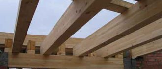
An example of an attic floor on wooden beams.
A floor on wooden beams is a load-bearing structure that separates adjacent rooms: floors, attic, underground. When constructing it, factors such as load-bearing capacity, sound and heat insulation, seismic resistance and heat resistance are taken into account. This structure regularly experiences loads and atmospheric influences, so it must meet the criteria of strength and wear resistance. According to their purpose, floors are classified into basement, interfloor and attic.
Selection of materials, design calculations
Types of floor beams
Design work includes planning the supporting structure, as well as calculation and selection of materials. For various floors, beams of the appropriate type are used. Most often, wooden beams are classified according to external characteristics: cross-section, composition and load-bearing capacity:
- board - a simple structural material used in the construction of sheathing and subfloors;
- I-beam - a structural material with a cross-section in the shape of the letter H. An I-beam allows you to reduce the total weight of the structure without loss in load-bearing capacity;
- LVL-beam is a beam made of laminated veneer, made by gluing peeled softwood: pine, spruce, larch. It has high strength levels under horizontal load. Used in the construction of rafter legs, interfloor beams, as well as ridge beams;
- combined beam - laminated veneer lumber, which includes veneer from several types of wood;
- four-edged timber - quadrangular-shaped lumber with 4 processed sides. It is most popular in the construction of any type of floor;
- double-edged timber (carriage) – lumber having 2 processed sides opposite to each other. Despite the relatively low strength indicators, the carriage is often used in the construction of interfloor ceilings;
- rounded log – milled lumber from a single piece of wood, characterized by the highest load-bearing capacity. Maximum load per 1 sq. m of beams of this type is 500 kg. However, due to their rounded shape, rounded logs are more often used in the construction of attic floors rather than interfloor floors.
When preparing beams, preference is given to coniferous species due to their increased strength and resistance to putrefactive processes. Analogues of spruce, larch and pine can also be acacia, oak or maple. These wood species are characterized by low humidity levels (from 12% to 14%). Over the years, the strength of beam floors increases due to the evaporation of moisture from their surface. After 5 years of drying, the strength of the timber approaches the strength of metal beams.
Horizontal load-bearing structures come in several types:
- interfloor covering on wooden beams;
- attic floor;
- basement floor.
Once the type and material of the beams have been determined, builders begin calculating the potential cross-section. The choice of beams with a particular cross-section directly depends on indicators such as:
- potential load (PL) per 1 sq. m. – the estimated mass that will have a permanent/temporary impact on the supporting structure. You can calculate the load yourself using one of the online calculators;
- span length (DS);
- step - the distance between adjacent beams (50 cm, or 1 m).
The suitable cross-section of the timber can be calculated using the tables below. To do this, just select the span length, expected load and step size.
| PN DP | 150 | 250 | 350 | 450 |
| 2 m | 50×100 | 50×100 | 50×100 | 50×120 100×100 |
| 2.5 m | 50×100 | 50×120 100×100 | 50×130 100×120 | 100×100 |
| 3m | 50×120 | 50×140 | 50×160 | 100×120 |
| 3.5 m | 50×140 100×100 | 50×160 100×130 | 50×180 100×150 | 100×160 |
| 4 m | 50×160 100×130 | 50×180 100×150 | 100×160 120×150 | 100×180 150×160 |
| 4.5 m | 50×180 100×140 | 100×160 130×150 | 100×180 150×160 | 100×200 150×180 |
| 5 m | 100×160 | 100×190 150×170 | 100×210 150×190 | 100×190 150×170 |
| 5.5 m | 100×180 | 100×190 150×160 | 100×200 150×180 | 100×220 150×200 |
| 6 m | 100×200 | 100×200 150×180 | 100×250 150×220 | 100×220 150×200 |
Table 1 — Section of beams at a step of 0.5 meters
| PN DP | 150 | 250 | 350 |
| 2 m | 100×100 | 100×110 | 100×120 |
| 2.5 m | 100×110 | 100×120 | 100×130 |
| 3m | 100×120 | 100×130 | 100×150 |
| 3.5 m | 100×140 | 100×160 | 100×180 100×160 |
| 4 m | 100×160 | 100×190 150×150 | 100×200 120×180 |
| 4.5 m | 100×180 150×160 | 100×200 150×180 | 100×220 150×190 |
| 5 m | 100×190 150×170 | 100×210 150×190 | 100×230 150×200 |
| 5.5 m | 100×200 150×170 | 100×220 150×200 | 100×240 150×210 |
| 6 m | 100×220 150×200 | 120×230 150×210 | 120×250 150×230 |
Table 2 — Section of beams at a step of 1 meter.
The number of beams for the floor is calculated using the following formula:
KB = DP/Sh, where:
- KB – number of beams of the established section;
- DP – span length;
- Ш – step.
The total number of beams depends on the number of spans.
Types of floors
A floor is a horizontal load-bearing structure made of beams that divides a building in height into functional zones or floors and maintains the strength of the entire structure. When building a house, the following types of floors are used:
- basement or basement floor;
- interfloor covering;
- attic floor.
Attic floor
Naturally, the most durable are metal beams in the form of a channel, angle or I-beam, made of high-strength steel. They are best used for the basement floor, as it bears the greatest load. Steel beams can be used to create long spans with large distances between beams. They are resistant to mechanical damage and rotting. However, due to their heavy weight, they are difficult to work with, and the high price of the metal increases construction costs.
Reinforced concrete floor beams can withstand heavy loads and are suitable for the construction of multi-story buildings. But for their installation you will need special equipment.
Basically, in the construction of private houses, wooden beams are used for floors. Wood is a reliable and environmentally friendly material that will not harm the residents of the house. Wooden beams are relatively inexpensive and light in weight compared to previous types, so they are easy to install. However, the tree is flammable, susceptible to rotting and bark beetle damage, and therefore requires pre-treatment.
Flooring technology using wooden beams
The maximum load-bearing load on the floor in residential premises is about 400 kg per 1 m2. Based on this value, beams of the appropriate section are purchased.
Section table for floor
In outbuildings, bathhouses, garages and other non-residential premises, the load varies from 100 to 300 kg. per m 2. Based on these indicators, beams with a smaller cross-section are selected (see Tables 1 and 2).
It is worth noting that each beam must have an allowance of 30 cm to the main length. This is necessary for installing the timber into the wall. So, for example, for spans of 3 meters, beams 3.3 meters long are used.
The beam installation technology has a number of features, among which are the following:
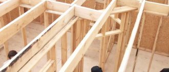
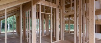
- The step depends on the type of building. In wooden buildings, the beams are laid parallel to each other at a distance of 1 meter, in frame houses - at a distance of 50 - 60 cm;
- The height of the beam should not be less than 1/24 of its length. Lower values reduce the strength of the structure;
- The optimal width of the beam is equal to its height, or half the height.
- The distance from the nearest beams to the stove should exceed 30 cm.
Basement floors are installed according to the “pie” principle. The supporting structure consists of the following layers:
- rough floor;
- waterproofing;
- insulation;
- load-bearing beams;
- logs;
- floorboards.
Construction of floors on wooden beams
Flooring technologies differ only in the type of beam fastening. When installing floor beams, hinged and recessed fastening methods are used. In the first case, metal canopies - beam supports - are mounted on opposite walls at equal distances from each other. Once all the supports are in place, the floor beams are snapped into them. This type of fastener is suitable for rooms with a strip foundation, brickwork, as well as in aerated concrete structures. The canopy will provide the beam with maximum fixation in the groove.
Fastening beams to metal canopies
With recessed fastening methods, a hole is cut at the base of the walls for the beams. Before installing the timber, this recess is lined with tow. In this case, the ends of the beams can be processed like a lock. For example, the tenon and hole are often ground down to a trapezoidal shape and fastened using the dovetail principle.
Fastening the timber using the dovetail system.
This method is considered the most complex and effective.
The basement floor installation technology consists of several stages:
- Marking and construction of nests. Using a building level and a measuring tape, the beam spacing is set along the first beam (order) from the foundation. After this, nests are drilled or cut at the marks with a cross-section 5-6 cm larger than the beam and a depth of 10 to 15 cm. The nests are lined with insulation.
- Installation of timber. The logs are mounted in recesses. The first and last beams fit tightly to the adjacent wall. The gaps between the nest and the beams are caulked with tow or other insulation. If necessary, fixing canopies are attached to the beams and the wall. In cases where it is impossible to drill nests, the ceilings are installed only on canopies (brickwork), or are secured using side slats (wooden walls).
- Floor screed. Boards are laid on the beams. The end of the first board is pressed tightly against the adjacent wall. The nails are driven in at an angle of 45 degrees. The end of the second board is pressed against the end of the first and attached to the beams using the same technology. Depending on the length of the span, 1 board can take from 4 to 10 nails. For floors in residential premises, five-piece boards and No. 12 nails are optimal.
After installing the basement floor, the subfloor is covered with facing material: fiberboard, laminate, linoleum and others.
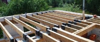
Plan of load-bearing floor structures
Hollow-core floors are supported on a load-bearing brick wall on the short side, at least 90 mm. If the support is cellular concrete - 120-150 mm. It is not recommended to rest the long side on self-supporting elements. For the construction of low-rise buildings, it is better to use slabs with a width of 1.8 m and a length of up to 7.2 m.
If the walls of the building are made of cellular concrete, it is better to use a ceiling made of the same material. On the short side they should be supported by load-bearing walls - 10-15 cm, and on the sides - 2-5 cm. To strengthen the structure, the plan should include a reinforced concrete belt made of a monolith that encircles the building and internal walls.
When drawing up a plan for a structure made of prefabricated reinforced concrete or cellular concrete slabs, it is important to make footnotes with the dimensions of the elements, indicate the sections of the monolith, the height of the support, the width of the reinforced concrete belt and the anchorage of the panels.
Mostly for floors, I-beams with a height of 16-27 cm are used. Floor beams should rest on the walls by 18 cm or more. To form a hard drive, you need to connect the beams together and attach them to the walls. The distance between the beams is 60, 77, 80 cm or 1, 1.1 m. The type of interbeam filler has the greatest influence on the step. It is better to fix the beams along the edges of the structure near the load-bearing walls (up to 5 cm from the edge of the beam to the wall). It is better to make elements of non-standard shape from monolithic concrete.
Upon completion of the arrangement of load-bearing elements on the walls of the building, they proceed to applying designations and dimensions
Installation of interfloor floors using wooden beams
The lower subfloor on interfloor floors is made of boards with a smaller cross-section.
The covering of the second floor using wooden beams is carried out using the same technology as the installation of basement structures. The main difference between the interfloor flooring and the floor flooring is the presence of a double subfloor. In this case, the lower subfloor is the ceiling of the 1st floor and is made of boards with a smaller cross-section.
The construction of attic and interfloor ceilings is carried out using the following technology:
- Load-bearing beams are installed in the landing slots.
- A windproof film is attached to the bottom using a construction stapler.
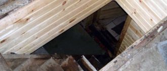
- The subfloor is attached below.
- Insulation is lined in the niches between the beams. This can be mineral wool, polystyrene foam, or ecowool based on split paper.
- Boards are laid on top of the insulation and the upper subfloor is screeded.
Ways to strengthen wooden floor beams
Conventionally, beam strengthening technologies can be divided into several types:
- restoration;
- reconstruction.
Restoration . This category includes methods such as reinforcement with wooden overlays, metal plates, carbon fiber wrapping, and prosthetics. Let's consider each of the options in more detail.
Wooden overlays
Installation of wooden overlays on a damaged beam.
Damaged beams (rotten, cracked, potentially weak) can be strengthened with wood overlays. To do this, the beam itself is cleaned with sandpaper or a plane and treated with an antifungal agent. A beam with a smaller cross-section is laid on both sides. The structure is tightened with cords and stitched with through bolts.
Metal plates
Schemes for fastening the damaged beam to plates (Fig. No. 1) and rods (Fig. No. 2).
The load-bearing capacity of broken logs is restored using metal prostheses using the technology described above. The hardware is applied to the cleaned and processed beam and tightened onto a series of through bolts.
Carbon fiber wrap
Schemes for fastening the damaged beam to plates (Fig. No. 1) and rods (Fig. No. 2).
Carbon fiber glued to damaged timber.
The technology for restoring floors using carbon fiber is simple and easy. To do this, the damaged area is glued with several layers of carbon material.
Prosthetics
Prosthetics using metal prostheses and onlays.
Prosthetics using metal prostheses and onlays.
Prosthetics are used to increase the strength and wear resistance of the joints between the timber and the wall. This is where the effects of corrosion and wear most often occur due to the maximum pressure. Preventive measures are taken at the stage of initial installation of the structure. Metal plates are sewn with bolts to the tenon of the timber. The reinforced structure is installed in the socket. An analogue of onlays is a metal prosthesis. It is drilled into the body of the beam and installed in a small hole in the wall.
The reconstruction category includes methods such as:
- installation of supports (columns, vertical beams);
- installation of additional beams.
Installation of supports
Support pile in the underground floor.
If the load-bearing capacity of the timber is insufficient, it is often reinforced with vertical supports. Installation of the pile allows you to redistribute the pressure from the beam to the support. This technology is most popular for renovation work in attics and under the floor.
Additional beams
Frequent step for timber with insufficient cross-section.
With a meter step, you can increase the load-bearing capacity of wooden floor beams using additional beams. To do this, the ceiling is completely dismantled and timber is installed in increments of 50 cm.