When building foundations or laying communications in the ground, it is necessary to dig pits and trenches. Excavation work must be accompanied by safety measures. They determine the rules for securing the sides and bottom. To determine the slope angle of the pit, a table is used. Its use makes it possible to select the desired level of inclination of the walls of the dug recess to its bottom for the soil at the construction site, so that collapse does not occur.
Types of earthworks
The construction of buildings and communication structures involves labor-intensive excavation work. They mean the development of soil when digging pits and trenches, its transportation, and storage.
Earthen structures are embankments and excavations. They can be permanent or temporary. The first ones are made for long-term use. These include:
- channels;
- dams;
- reservoirs;
- dams and other structures.
Temporary excavations are trenches and pits. They are intended for subsequent construction work.
A pit is a recess, the width and length of which practically do not differ noticeably in size. They are necessary for constructing foundations for buildings.
The trench is a furrow of great length compared to its cross section. It is intended for installation of communication systems.
According to the requirements of GOST 23407-78, digging pits and trenches in populated areas, areas of traffic or people must be accompanied by the creation of protective fences. They are installed around the perimeter of the work area. Warning signs and inscriptions are placed on them, and even signal lighting is used at night. Bridges are also specially equipped for the movement of people.
Slopes are the inclined side walls of excavations or embankments. An important characteristic is their slope (steepness). The horizontal surfaces surrounding the slopes are called berms.
The bottom of the recess is understood as its lower, flat part. The edge is the upper edge of the created slope, and the bottom is the lower part.
Excavation work at a construction site
When operating earthen structures, they must not:
- change its outlines and linear dimensions;
- to sag;
- eroded by water or susceptible to precipitation.
The laying of water pipelines, underground power lines, sewerage, and the construction of foundations for buildings cannot be done without digging trenches or foundation pits. In construction, special definitions have been adopted to designate structural elements of this type. All work must be carried out in strict compliance with safety rules in order to minimize the possibility of accidents.
Types of pits
Digging holes for the foundation of a structure is a responsible task that requires a lot of time, money, and labor. Today, pits are usually divided according to the following criteria:
- the presence of slopes;
- the use of fastenings designed to prevent soil slides;
- type of side surfaces (walls).
The walls of the pits can be:
- vertical;
- inclined;
- stepped.
Pit
In order to carry out excavation work correctly, research is first carried out at the construction site. These activities include the following operations:
- analysis of soil properties: establishing its group and type;
- determination of loads from the building being erected;
- calculation of excavation depth;
- establishing the presence of old communications;
- determining the depth of groundwater;
- analysis of local weather conditions.
The choice of work method is determined depending on the following factors:
- type and dimensions of the structure being built;
- foundation depth;
- volume of upcoming activities.
If you plan to construct a shallow foundation of a strip or columnar type, then the soil can be developed without the involvement of machinery, manually. When it is necessary to build a house with a basement or ground floor, then the work will require the use of earth-moving mechanisms.
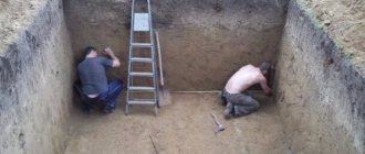
To extract the bulk of the soil from the excavation, various types of excavators equipped with a backhoe or a straight shovel are often used. Work related to digging a pit should be carried out without disturbing the density of the soil at the bottom of the foundation. This requirement is implemented in practice by its shortfall, the value of which ranges from 5 to 20 cm.
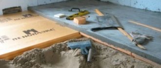
Workers clear the earth from the sides and bottom of the excavation to the planned level manually. In this case, you should definitely ensure that its walls are strengthened with the help of slopes, or through the installation of special structures. Precipitation and rising groundwater in spring and summer, exposure to frost in winter - all this contributes to the destruction of the pit.
The soil from the pit must be immediately removed or placed on the construction site no closer than 1 m from its edge. A drainage system is created to drain soil water.
An important point when digging pits is to create a working space of the required dimensions according to the rules. It should occupy at least half a meter from the foundation formwork to the bottom of the slope. The steepness of the pit slopes is selected according to the tables or graphs given in SNiP 3.02.01-87.
When a project is required to develop a pit
The part of the project in which excavation work is carried out at the site is called the PED (excavation project). Such a project is drawn up when the development depth exceeds 2 m (this could be a house with a basement), and also when, for the safety of work, it is necessary to strengthen the walls or make a deep dewatering.
PRC (or PPR of the pit) includes plan and sectional drawings, technological and other diagrams that contain information, right down to the locations of earth-moving equipment and dump trucks.
If a pit is being developed next to an existing structure, or its depth exceeds the level of the latter, the project determines measures against soil settlement and deformation of structures.
This could be the construction of sheet piling walls, strengthening of soils by cementation or silicification, or the construction of a new, deeper foundation under the old one.
Protection of foundations of existing buildings
How the shape of the pit walls depends on its depth
The properties of the soil and the presence of groundwater in it determine the structure of the pit, which can have vertical walls or flat ones.
Vertical ones without fastenings can be done in dense, dry soils, and only when the pit does not remain open for a long time.
Stepped pit walls
If there are vertical slopes (if there are no structures nearby), the depth cannot exceed:
- in hard clays and loams – 3 m;
- in semi-solid clays and loams – 2 m;
- in hard-plastic clays – 1.5 m;
- in fluid clays and hard sandy loams - 1.25 m;
- in sandy, gravel and loess soils – 1.0 m.
When it is necessary to dig to great depths, flat (sometimes stepped) walls are provided in the pit, or one of the options for fastening the walls is chosen.
Sheer walls of the pit with anchorage
When the depth is more than 5 meters, the steepness of the slopes is taken according to the table in SNiP and depends on the type of soil. This parameter is the ratio of the depth to the projection of the slope onto the horizontal (in the diagram below).
Drawing: pit slope slope 1:1
Determining the dimensions of the pit
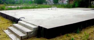
The depth of the pit is an important parameter, which is determined by the addition of the thicknesses of the foundation and underlying layers. These are: sand and crushed stone cushions, concrete preparations and reservoir drainage.
There is no difference whether a pit is dug under a strip foundation or under a monolithic slab. It can also go significantly deeper when the building has a ground floor or basement.
Depth – the sum of all layers, starting from ground level
Basic parameters when calculating the dimensions of a pit
The dimensions of the bottom in plan are determined during the design, taking into account the parameters of the foundation and the method of construction, the required space for formwork, the convenience of concreting or installing prefabricated elements.
Often the dimensions of the pit at the bottom and at the top differ slightly, because flat walls increase the volume of excavation work. In practice, vertical slopes are more often made, despite the need for strengthening.
Types and purpose of trenches
Laying trenches for various communications is the most common type of excavation work. Digging them by hand is slow and expensive, so they often use equipment that they buy or rent.
According to their purpose, recesses of this type are divided into the following types:
- for grounding;
- plumbing;
- cable;
- gas pipelines;
- drainage (drainage);
- sewer.
Digging a trench with an excavator
According to the design of the trench, there are 3 types:
- rectangular;
- trapezoidal;
- mixed.
Inside trenches without sloped side walls, spacers are installed to increase the level of safety for people. Strengthening the slopes is not required, because they are made for the purpose of protection against landslides. Trenches intended for laying communications are dug at varying depths using different techniques.
Soil: groups and types
Due to the fact that earthworks are created in soils, you should definitely know their basic characteristics. The appropriate type of foundation directly depends on them. The choice is made taking into account achieving the highest possible level of reliability and durability of the foundation being built.
The main properties of the soil are determined by the following factors:
- shape, size, strength, arrangement of particles included in its composition;
- the degree of relationship between them;
- the ability of constituent substances to solubilize and absorb moisture.
Soil is characterized using the following coefficients:
- compressibility;
- friction;
- plasticity;
- loosening.
The classification involves dividing soils according to various criteria. There are the following types:
- sandy;
- dusty;
- clayey;
- rocky;
- clastic.
Different types of soil
Depending on the water content, soil is distinguished:
- dry (up to 5% moisture present);
- wet (5-30%);
- wet (contains more than 30% water).
The division into groups is presented in the table below.
| Category | Included soil varieties |
| 1 | sandy loam, sand, light loam (wet), peat, plant layer soil |
| 2 | light damp clay, fine to medium gravel, loam |
| 3 | dense loam, medium and heavy (loose) clay |
| 4 | frozen soils (clayey, loamy, peat, sandy, sandy loam, plant layer), heavy clay |
| 5 | fragile limestone and sandstone, strong clayey shale, permafrost (with admixtures of crushed stone, pebbles, boulders, gravel up to 10%), moraine and river (with large boulders and pebbles content up to 30%) |
| 6 | strong shales, clayey sandstone, marly limestone, fragile serpentine and dolomite, fluvial and moraine (inclusions of boulders and pebbles - up to 50%), permafrost (with a share of gravel, boulders, pebbles, crushed stone - up to 20%) |
| 7 | hard limestone and sandstone, dolomite, serpentine, mica and silicified schists, marble, permafrost (stone components account for up to 70% of the volume) |
Soils are also divided into the following types:
- quicksand;
- soft;
- average;
- strong.
The structure and properties of the soil at the construction site play a major role in calculations during foundation design. This is due to the fact that depending on the type of soil its bearing capacity is determined. Also, each variety reacts differently to weather conditions.
Excavation plan, requirements for them
Excavation work takes place in a number of stages. They are prescribed in SNiP 3.02.01-87. The main stages of the process are as follows:
- carrying out preparatory activities;
- experimental production part;
- creating a pit or trench;
- carrying out control activities;
- acceptance of completed work.
SNiP 3.02.01-87 provides the following requirements:
- developing a working draft is allowed only by specialists who have the necessary qualifications and experience;
- communication and coordination of actions in matters of design, construction, and engineering solutions must be ensured between them;
- It is constantly necessary to monitor the quality of construction work on site;
- the project must be implemented by personnel with appropriate qualifications;
- the erected structure may only be used for its intended purpose in accordance with the design;
- Maintenance activities for the structure and accompanying utilities must maintain it in a safe, working condition throughout its operation.
When digging pits and trenches, you must adhere to the following instructions:
- rules for organizing their construction;
- standards for conducting geodetic work;
- labor protection standards;
- sections of fire safety rules relating to construction work.
Fenced construction site with fixed pit walls.
Earthen structures must be created strictly according to the current design.
Carrying out work with explosives requires compliance with appropriate safety rules during their production.
The materials, structures, and products used in the work must meet the requirements of the standards and the project. Their replacement may be carried out only after prior agreement with the organization that developed the documentation and the customer.
The following types of control during excavation work are distinguished:
- input;
- operating;
- acceptance
Control is carried out in accordance with SP 48.13330.
Acceptance of work occurs with the preparation of the necessary documentation (acts) confirming its completion.
The considered requirements in individual construction are greatly simplified. Small buildings are often erected without any projects, and the depth of excavations does not exceed 1.5-2 m, but safety precautions must always be observed.
Safety measures when digging pits
The soil from the side walls of a pit or trench, as a result of the action of gravity on them, can move and fill the bottom of the excavation. Due to the uncontrolled collapse of earth masses, accidents to people are possible. Also, destruction leads to an increase in labor costs and money: it will be necessary to restore the planned contour of the excavation and backfill the foundation with a large volume of soil.
In order to prevent crumbling and reduce the possibility of material losses to a minimum, it is necessary to correctly calculate, at the design stage, in accordance with SNiP 111-4-80, the steepness of the slopes of the excavation being created.
If the depth of a trench or pit, on average, exceeds 1.25 meters, then it is necessary to strengthen their walls in order to prevent possible collapses and earth slides. Along the contour of the excavated structures, strips should remain free from the excavated soil mass, the minimum width of which is more than 0.6 m. The earth from the excavation should not roll back.
The parameters of the side slopes must be determined correctly before developing the pit. This will allow:
- prevent the possibility of collapses;
- perform the optimal amount of excavation work;
- will eliminate the cost of altering slopes during construction work.
Landslide prevention is a major safety concern for personnel.
Compliance of slopes with optimal angles of inclination for a given type of soil minimizes monetary and labor costs for backfilling and rework.
Slope formation
Before starting work, geological and hydrological surveys of the building site are carried out. If there is soil water, unstable soil, or if it is necessary to dig a hole more than 5 m deep, a project is created for the identified individual conditions.
According to SNiP 111-4-80, for non-moist soils with a uniform structure, vertical side walls can be left when digging trenches or pits. In this case, there should be no structures near the excavations and no groundwater. The permissible depth of excavations for different soils with vertical walls is for:
- gravel, sand – 1 m;
- sandy loam – 1.25 m;
- clayey and loamy - no more than 1.5 m;
- very dense - 2 m.
In pits with a depth of about 1.25 m, it is required to use stepladders that will rise above the ground to a height of at least 1 m. In deeper excavations, flights of stairs are used.
The side surfaces of the pits may be strengthened with construction. If there is a possibility of additional loads or slopes being washed out, they are covered with film or shotcrete is carried out (concreting with a thin layer).
Stage No. 3: Digging and moving utilities
Before you begin the digging process, you need to determine the locations of pipes, electrical networks and sewers, as well as their technical features. Communications should be disconnected, dismantled and moved to another location. In this case, it is impossible to do without coordinating the work being carried out with the responsible authorities.
After receiving permission to dismantle utilities, the technical process must be included in the general construction plan. The project and estimate are verified, the scope and work plan are specified, after which a corresponding act is drawn up and approved.
When starting to dig, the turf is removed and the soil is loosened. The organization of ledges is necessary on slopes at the base of the embankment - they are made at a slope of up to 0.02, directed along the level of the slope, and have dimensions up to 4 meters in width. If embankments are characterized by high humidity, drainage or avalanche control measures are necessary.
The process of digging a pit is carried out in two ways:
- - Manual. It is carried out in areas where there are no access roads for equipment. Typically, such work is carried out for small-sized pits. The tools used are spades, shovels, wheelbarrows for removing soil and clotting machines.
- – Mechanized. If the construction site has access roads, then equipment such as excavators, trucks, bulldozers and loaders is used. This method allows you to reduce the time and effort for arranging a pit - on average, the work takes about two days, depending on the size of the pit.
In the process of excavating soil for a foundation pit, it is necessary to take into account the characteristics of the soil:
- – if it is dense, a depth of up to 2 meters is permissible;
- – for loamy and clayey soils – up to 1.5 meters;
- – excavation in sandy loam soil is allowed up to 1.25 meters;
- – if the soil is sandy or gravelly – only up to 1 meter.
After digging a pit, it is necessary to take care of the reliable strengthening of the walls.
Slope table
When you need to dig a hole at least 1.5 m deep, then you should take the slope angle of the pit according to the table given in SNiP 111-4-80. It takes into account both the type of soil and the depth of the foundation.
In construction literature, standards, and rules, the steepness of an excavation slope is measured in degrees (angle), or as the ratio of its height to the foundation.
A table of slope steepness for pits of different depths and on different types of soil is presented below.
Despite the presence of slopes, there remains the possibility of collapse of the soil mass under the influence of the weight of the equipment involved. Therefore, the distance from the parking lot of cars to their sole is also regulated by SNiP.
When there are different types of soil on a construction site, then the steepness of the slopes is chosen according to its most unstable type. It is recommended to remove existing inclusions of boulders and stones using an excavator to prevent the possibility of landslides and collapses.
The walls of excavations up to 3 m deep are secured according to design instructions.
If the cohesion of the soil in the working area changes for the worse when water gets into it, during drying, or under the influence of low temperatures, then it is recommended to equip slopes of lesser steepness, or with indents.
When the side surfaces of pits up to 3 m deep with steps are formed, the width of the latter must be at least 1.5 m. In this case, slopes must also be made.
Machine operation near slopes
If the design depth of the excavation exceeds 5 m, or the steepness of the pit wall differs from the table value, then the stability of the slopes must be calculated.
Pits or trenches dug during autumn or winter frosts must be inspected during spring thaws and the stability of their slopes determined.
With the slope angles discussed in the table for each type of soil and pit depth, workers can be in the excavation without the need to secure the slopes. If the slopes have been moistened, then before starting work they are inspected for cracks and peeling.
Pit slopes.
The angle of repose depends on the angle of internal friction, adhesion force and pressure of the overlying layers. In the absence of adhesion forces, the limiting angle of repose is equal to the angle of internal friction.
The steepness of the slope depends on the angle of repose.
The steepness of the slopes of excavations and embankments is characterized by the ratio of height to foundation:
m – slope coefficient.
Source: Collection of auxiliary materials for the development of a manual on the reclamation of lands disturbed during quarrying and highway construction
3.30. Angles of natural repose of soils
| Priming | Relative soil humidity | |||||
| dry | wet | wet | ||||
| degrees | height to ground ratio | degrees | height to ground ratio | degrees | height to ground ratio | |
| 1 | 2 | 3 | 4 | 5 | b | 7 |
| Pebbles | 35 | 1:1,5 | 45 | 1:1 | 25 | 1:2,25 |
| Gravel | 40 | 1:1,25 | 40 | 1:1,25 | 35 | 1:1,5 |
| Oily clay | 45 | 1:1 | 35 | 1:1,5 | 15 | 1:3,75 |
| Bulk soil | 35 | 1:1,5 | 45 | 1:1 | 27 | 1:2 |
| Vegetable soil | 40 | 1:1,25 | 35 | 1:1,5 | 25 | 1:2,25 |
| Coarse sand | 30 | 1:1,75 | 32 | 1:1,5 | 27 | 1:2 |
| Sand medium | 28 | 1:2 | 35 | 1:1,5 | 25 | 1:2,25 |
| Fine sand | 25 | 1:2,25 | 30 | 1:1,75 | 20 | 1:2,75 |
| Light loam | 40 | 1:1,25 | 30 | 1:1,75 | 20 | 1:2,75 |
| Loam, light clay | 50 | 1:0,75 | 40 | 1:1,25 | 30 | 1:1,75 |
| Sand with gravel and pebbles | 35 | 1:1,5 | 40 | 1:1,25 | 30 | 1:1,75 |
| Sandy loam, semi-solid | 40 | 1:1,25 | 30 | 1:1,75 | 15 | 1:3,5 |
| Crushed stone | 40 | 1:1,25 | 45 | 1:1 | — | — |
| Riprap | 40 | 1:1,25 | 45 | 1:1 | — | — |
3.31. Angles of natural repose of rocks (loose state)
| Breeds | Angle of repose, degrees, for rock | ||
| dry | wet | wet | |
| 1 | 2 | 3 | 4 |
| Vegetable soil | 40 | 35 | 25 |
| Coarse sand | 30-35 | 32-40 | 25-27 |
| Sand medium | 28-30 | 35 | 25 |
| Fine sand | 25 | 30-35 | 15-20 |
| Loam | 40-50 | 35-40 | 25-30 |
| Oily clay | 40-45 | 35 | 15-20 |
| Gravel | 35-40 | 35 | 30 |
| Peat without roots | 40 | 25 | 15 |
| Rocky | 45-60 | ||
The angle of repose is the greatest angle that can be formed by a free slope of bulk material with the horizon in a state of equilibrium.
Methods of excavation work, mechanisms used
Depending on the soil, different equipment is used in the construction of trenches and pits, and various methods are used to develop construction sites. They differ in labor intensity and the level of required material costs. According to SNiP 111-4-80, the following methods are identified:
- hydromechanical;
- mechanical;
- carrying out blasting operations.
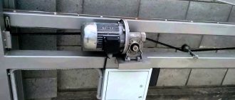
The mechanical method of developing pits and trenches is the main one. Its essence lies in digging soil using earth-moving (excavator) machines, or earth-moving and transport machines (scrapers, bulldozers, graders).
The hydromechanical method is based on eroding the soil mass with a jet of water from a hydraulic monitor. Then the resulting solution is sucked into the dredge.
Blasting works are used mainly in suburban construction. First, holes (wells) are drilled in the ground. Then they put explosives in them and detonate them. The resulting loose mass is removed using machinery.
Mechanical method of digging holes
The mechanical method consists of a number of stages:
- loosening the soil;
- development of rock mass;
- its transportation;
- leveling, compacting side slopes and bottom.
Work on creating recesses using a hydromechanical method takes place in the following sequence:
- designate the work site area using fences, inscriptions, and warning signs;
- according to the standards, a hydraulic monitor is installed, manually controlled by the operator: the distance from its nozzle to the wall of the pit must be no less than the height of the excavation, and to the nearest overhead power line - at least two intervals over which a stream of water can be supplied by this equipment;
- Slurry pipelines and water conduits are placed behind the security perimeter of power lines;
- protect the dumping areas of the reclaimed earth mass;
- produce erosion and excavation.
It is prohibited to operate the hydraulic monitor during a thunderstorm.
Conducting blasting operations is regulated by relevant rules.
When mechanical loosening of the earth mass is carried out using the impact method, then workers should not be within a radius of 5 m from the site of loosening.
Any equipment must be located during operation in accordance with current standards and rules. Deviation from them often causes accidents.
The steepness of the slopes depending on the type of soil and the depth of excavation
Home Favorites Random article Educational New additions Feedback FAQ⇐ PreviousPage 6 of 58Next ⇒
| Names of soils | Steepness of slopes (ratio of its height to foundation) at excavation depth, m, no more | ||
| 1,5 | |||
| Unfilled sandy and gravel sandy loam loam clay loess and loess-like | 1:0,67 1:0,5 1:0,25 1:0 1:0 1:0 | 1:1 1:1 1:0,67 1:0,5 1:0,25 1:0,5 | 1:1,25 1:1 1:0,85 1:0,75 1:0,5 1:0,5 |
5.3. Construction site preparation
To create favorable conditions for the start of construction work, preparatory work is carried out in advance.
Work to prepare a construction site for new construction includes: fencing the site; clearing the area and demolishing existing buildings; rerouting of interfering utility networks; protection of the territory from surface water runoff; laying temporary communications and roads; arrangement of temporary household, storage, cultural, administrative and other premises.
After clearing the territory, they carry out work to create a geodetic support network, install demolition and carry out a geodetic breakdown of buildings and structures.
The scope of preparatory work for the reconstruction of an existing enterprise largely depends on local conditions. Builders try to make maximum use of the existing utility networks, household and administrative services are often located in temporarily vacated premises, buildings are erected according to the capital construction plan of the reconstructed enterprise, which are temporarily used for construction needs, etc.
Aboveground and underground utilities, communication and power lines and other structures that impede the work are dismantled or moved to places determined by the project, under the supervision of specialists from relevant organizations.
During the preparatory period, sometimes reaching 40% of the duration of the entire construction, it may be necessary to create an industrial production base for the production of building products and parts, mortar and concrete mixtures; connect the construction site with main roads, energy and utility networks, etc.
The success of all major construction and installation work on the construction or reconstruction of buildings and structures, utility networks and launch complexes largely depends on the thoroughness of completing the tasks of the preparatory period. The scope of work during the preparatory period is determined in the PIC and specified in the PPR.
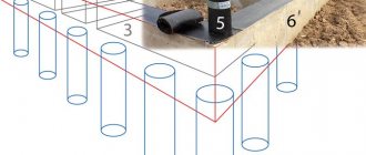
Drainage of the site and work areas. Lowering the groundwater level or draining surface water (overflow) is usually carried out using a water lowering or drainage device. More often, drainage ditches or embankments from the upland part of the site are used for this (Fig. 5.3, a).
If there is a significant influx of groundwater, open or closed drainages are installed. Open drainages represent co-
Fig, 5.3. Drainage using:
o - embankment of the site; 6
- conventional drainage;
c
- drainage with a perforated pipe;
( - slope; / -
earthen enclosure;
2
- drainage ditch;
3
- pit;
4
- construction site; 5 - local soil;
6
- drainage material;
7, 8
- fine- and coarse-grained sand, respectively;
9
- gravel;
10
- insulation layer;
II -
perforated (with holes) pipe
broken ditches, at the bottom of which layers of filter material are laid: coarse sand, crushed stone or gravel. Closed drainages (Fig. 5.3, 6, c)
- these are trenches developed below the level of seasonal freezing of the soil and filled with layer-by-layer filtering materials. Along the bottom of the drainage, you can lay a pipe with holes in the side walls (perforated) to drain water.
To protect against water influx, ice walls made of frozen soil or impermeable screens can be used.
Artificial freezing (Fig. 5.4, a)
carried out using a solution of salts with a low freezing point (calcium chloride, etc.) cooled to a negative temperature. To do this, freezing columns consisting of two pipes are lowered into drilled wells: an internal one and an external one with a closed end. A brine solution (coolant) cooled below the required ground temperature is passed between these pipes. The soil near the walls of the outer pipe freezes and, gradually increasing in diameter, forms an ice curtain.
A thixotropic impervious screen can be installed after driving metal or wooden sheet piles
'L
b
7J7
1J
| JJ |
| 13\ | / | ^■14 g'5 |
| /// /// | /// / | |
| g( about s: g- a ■ *■ > | \ | |
| «—~ |
7 17 16 g
Rice. 5.4. Artificial fencing of excavations from groundwater: a -
soil freezing scheme;
6 —
device of an anti-filtration screen
using
sheet pile injectors;
c, d -
the
same, using
bar machines and a water-air jet;
d -
installation of a soil-concrete screen;
/ - freezing columns; 2—
pillars of frozen soil;
3 -
pit;
4
- outer pipe;
S -
inner pipe;
b—surface of the frozen pound; 7—suspensions; 8 -
pipes for supplying suspension;
9 -
sheet piling, extracted from the ground;
10 -
the same, deflated;
11 —
tractor;
12
— working body with bars;
13
- pound displaced to the surface;
14—
rod;
75—guide; 16—
injection head;
P -
monitor head
plates Then the individual sheet piling injectors are gradually removed, and a solution of bentonite clay, which has water-repellent properties, is injected in their place (Fig. 5.4, 6).
A suspension of bentonite clay can be pumped into slots cut by special machines - bars (Fig. 5.4, c)
or supplied through wells under high pressure using a water-air jet (Fig. 5.4,
d).
The suspension erodes the gap in the soil and fills it.
Soil concrete screen (Fig. 5.4, d)
it works like this. Drill rods with cutting and mixing blades are immersed in the ground, and a water-cement suspension is injected through them. When the rods are lifted back with rotation, the blades open, the soil is mixed with the suspension and subsequently hardens, forming an anti-filtration curtain.
When developing excavations in soils, open drainage or artificial lowering of the groundwater level can be used.
Draining the excavation with an open drainage system is used when there is a small influx of water and consists in the fact that the bottom of the excavation is given a slight slope (Fig. 5.5) to the sump, the size of which in plan corresponds to 1 x 1 m. Water is pumped out from the pits with pumps: piston pumps with a small influx of water; centrifugal for clean water; diaphragm for contaminated water.
The water pumped out from the sump well is discharged through pipes or trays. When there is a large influx of water, the walls of the pits are strengthened to prevent collapse.
| Rice. 5.5. Open drainage: 1 - sump well; 2 — sleeve; 3— pump; 4 - tray |
Despite the simplicity and economy of open drainage, work using this method can be complicated by the constant presence of water and possible disruption of the soil structure of the walls and base. Therefore, it is often necessary to use an artificial lowering of the groundwater level using wellpoints (Fig. 5.6, a, b),
immersed in the ground around the perimeter of the pit.
In light wellpoint installations (LIU), water is pumped through one pipe using conventional methods; in ejector wellpoint installations (EIU), each wellpoint filter consists of two pipes; water, on the contrary, is pumped and, passing through a special device - the ejector, creates an air vacuum (Fig. 5.6 , c, d).
With ejector wellpoints, the groundwater level (depression curve) can be lowered to 17...18 m, with light wellpoints - to 4...5 m. Therefore, light wellpoints are sometimes installed in two and three tiers.
In soils with a low filtration coefficient, the phenomenon of electroosmosis can be used, for which it is necessary to drive metal rods or pipes at a distance of 0.5 ... 1 m from the wellpoints and connect them to the positive pole of a direct current source (anode), and the wellpoints to the negative (cathode) . A directed current begins to flow from the anode to the cathode, under the influence of which water moves in the soil in the same direction (the direction of water movement in Fig. 5.6, d
indicated by arrows).
Rice. 5.6. Schemes of wellpoint installations:
A
— pit with light wellpoints in one tier;
6
- the same, in two tiers;
c, e -
ejector wellpoint unit and filter unit;
d
- electrical dehumidification diagram;
1
- working pump;
2 -
drainage collector;
3 -
wellpoint;
4—
groundwater level after drainage;
5 -
pressure pump;
6 —
steel rod (anode);
7—filter unit; S—
outer pipe;
9
— internal pipe with an ejector device;
10—
vacuum;
11 —
ball valve; GWL - level
groundwater
If it is necessary to lower groundwater by 20 m or more, tube wells with artesian pumps can be used.
Clearing the area and demolishing buildings. In accordance with the preparatory work project, part of the green space at the construction site is protected from damage and replanted in new places. Trees and shrubs that are not subject to cutting down and replanting are fenced off, and the rest are cut down with mechanical or electric saws, the thick roots of the stumps are cut with rippers or bulldozers, after which the stumps are uprooted using tractor winches, sometimes using pulleys (Fig. 5.7).
Trees with a diameter of up to 25 cm are felled by bulldozers, and bushes are cut with brush-cutting tractors. To crush large stones and split large stumps, blasting methods are sometimes used.
The fertile layer of soil to be removed is moved by bulldozers to specially designated areas (hills), and then used in landscaping areas or taken to other places for land reclamation. The complex of works on removing, transporting and applying a fertile layer of soil to unproductive lands in order to improve them is called “digging” by builders.
The thickness of the removed fertile and potentially fertile layers is established based on an assessment of the fertility of individual
Rice. 5.7. Uprooting stumps with a tractor skidding winch: a -
straight pull uprooting;
b
- uprooting using a double and triple pulley;
/ - uprooted stump; 2
- anchor rope;
3
- traction rope;
4
— tractor with winch;
5
- anchor stump;
6
- auxiliary anchor stump; 7 - block
| Loading battle |
Dismantling (destruction)
Rice. 5.8. Demolition of buildings using excavators equipped with: o - a bucket; b
— hydraulic hammer;
in
- ball-baby;
g
- raalamyvatel;
d
— hydraulic shears
soil horizons. Usually, if the thickness of the fertile layer exceeds 10 cm, it is removed.
When vertically planning areas that are later used for squares, parks or green spaces, the soil cover is preserved, and storm water is drained through the installation of temporary drains.
During demolition, wooden buildings are disassembled into elements for the purpose of further use of suitable wood. When disassembling, each detachable element must be pre-secured and in a stable position.
During disassembly, metal structures are secured and then cut with oxygen torches. Reinforced concrete buildings are dismantled in accordance with the demolition scheme, which ensures the stability of the structure as a whole. In structures, the reinforcement is first exposed, the resulting individual blocks are secured, the reinforcement is cut and the blocks are broken off. The maximum mass of such a block, in accordance with safety requirements, should not exceed half the crane’s lifting capacity at the maximum hook reach.
The sequence of demolition of buildings is the reverse of the installation sequence. Prefabricated reinforced concrete structures that cannot be separated element by element are destroyed as if they were monolithic. When developing, it is advisable to use excavators with various special effective attachments (Fig. 5.8). For example, the “scissors” equipment based on the KATO ND 1500 GYS excavator has a cutting force of 2649 kN.
5.4. Soil strengthening
Usually, when constructing earthen structures, their side walls are arranged in such a way that the angle of repose is less than the angle of repose. However, very often, especially in the city,
In such conditions, it is impossible to arrange slopes due to cramped conditions. In addition, when wet, even under the conditions of properly constructed slopes, the upper part of the excavation may collapse. Such cases occur due to the fact that when the soil gets wet, its angle of repose can change sharply (for example, for clay from 45 to 15°, for loam from 50 to 20°, etc.).
In such conditions, it is necessary, along with limiting the flow of water, to strengthen the side walls of earthen structures with fastenings (Fig. 5.9).
Sheet piling is an expensive method used when excavating excavations in water-saturated soils near existing buildings and structures. The sheet pile is driven in before the excavation is developed, thereby ensuring a stable and natural state of the soil outside it.
The cantilever type fastening consists of racks - piles, grounded with their lower part in the ground deeper than the bottom of the excavation. They serve as supports for shields or boards that directly bear ground pressure. A cantilever-type fastening is advisable for excavation depths of up to 5 m. In trenches of considerable depth, a cantilever-spacer fastening is used, which differs from a cantilever fastening in that spacers are installed between the posts in their upper part perpendicular to the axis of the trench.
Spacer (frame) fastening - the simplest in design - is used when constructing trenches up to 4 m deep in dry or low-moisture soils. It consists of posts, horizontal boards or boards and spacers that press the boards or boards against the walls of the trench.
and in g about f
Fig. 5.9, Securing soil from collapse:
A -
diagram of the collapse of the upper part of the slope when wet;
b
- inventory tubular spacer frames;
c, d, e -
fastenings: tongue-and-groove, cantilever, cantilever-spacer, respectively;
f, g -
spacer and strut fastenings;
1 -
anchor pile;
2
— guy;
3 -
lighthouse pile (support post);
4 -
guide pile;
5— sheet piling; 6—
shields (boards); 7— spacer racks
frames; 8—
spacer
Inventory tubular spacer frames are the most effective (Fig. 5.9, b) due to their low weight and ease of installation and dismantling. They are set to the required width by turning the couplings with screw threads.
When excavating trenches, wooden or metal fasteners are installed with an excavator directly when excavating the excavation. The excavator installs the blocks and, as the trench deepens, presses their upper ends with a bucket (see Fig. 4.4).
When creating permanent waterproof curtains around the excavations being developed or in the case of increasing the bearing capacity of soil foundations, the following methods of artificial soil consolidation are used: cementation and bituminization; chemical, thermal, electrical, electrochemical, mechanical, etc.
Cementation and bitumenization involves injecting cement mortar or heated bitumen. These methods are used for porous rocks with a high filtration coefficient, as well as fractured rocks.
Sandy and loess soils are fixed by chemical means (silicatization) by injecting chemical solutions into them.
Thermal consolidation involves burning loess soils with hot gases pumped through wells into their pores. Gases are supplied into the soil along with air through heat-resistant pipes in drilled wells.
Wet clay soils are consolidated electrically. The method involves using the effect of electroosmosis, for which a direct electric current with a field strength of 0.5... 1 V/cm and a density of 1... 5 A/m2 is passed through the soil. In this case, the clay dries out, becomes compacted and loses its ability to heave.
The electrochemical method differs from the previous one in that, simultaneously with an electric current, solutions of chemical additives (calcium chloride, etc.) are introduced into the soil through a pipe, which is the cathode. Due to this, the intensity of the soil consolidation process increases.
The mechanical method of strengthening soils has the following varieties: arrangement of soil cushions and soil piles, compaction of pits, etc.
The construction of soil cushions consists of replacing the weak foundation soil with another, stronger one, for which the weak soil is removed, strong soil is poured back with layer-by-layer compaction.
When constructing soil piles, a leader pile is driven into weak soil; after removing the leader, soil is filled into the resulting hole with layer-by-layer compaction.
Compaction of pits is carried out using heavy rammers suspended on the crane boom. This method is less
more complex than the method of soil cushions, since it does not require replacement of the foundation soil.
Compaction of pits of significant size can be carried out with smooth or pad rollers, tamping machines, vibratory rollers and vibratory plates.
5.5. Determination of the volume of excavation work
The volumes of excavated soil are measured in cubic meters of dense solids. For some processes (surface compaction, grading, etc.) volumes can be measured in square meters of surface.
Calculating the volumes of excavated soil comes down to determining the volumes of various geometric shapes. It is assumed that the volume of soil is limited by planes; individual irregularities do not significantly affect the accuracy of the calculation.
In industrial and civil construction, it is necessary to mainly calculate the volumes of pits, trenches, excavations and embankments when planning sites vertically.
Volume of the pit (Fig. 5.10, o)
where And
— pit depth;
a, b -
lengths of the sides of the pit at the base;
o,, 6, are
the lengths of the sides of the pit at the top
(al= a +
+
7Нт; b{ = b
+
2Нт);
t is the slope coefficient (standard value according to Table 5.4).
To determine the volume of backfilling of the pit sinuses, when its volume is known, it is necessary to subtract the volume of the underground part of the structure from the volume of the pit (Fig. 5.10, b):
where a', b' ~
dimensions of the building in plan.
When calculating the volumes of trenches and other linearly extended structures, their longitudinal profiles are divided into sections between fracture points. For each such section, the volume of the trench is calculated separately, after which they are summed up. So, the volume of the trench in the area between points / and 2
(Fig. 5.10,
c)
is calculated using the formulas:
K,_2 = (Ft
+
F2)
£1-2/2 (overpriced) or
Fj_2 = F^
Li_2 (lowered),
where Fu F2
— cross-sectional area at the corresponding points of the longitudinal profile;
F^ is
the cross-sectional area at the middle of the distance between points
1
and
2.
Rice. 5.10. Schemes for determining the volume of excavation work:
a, c
— geometric schemes for determining the volume: respectively, the pit and
trenches; 6 —
pit section;
d
- site plan with slopes (with a line of zero
works and a schematic representation of geometric figures to determine
volumes of developed soil); C - building; O - backfill
More accurately
or
F2/2-m
(I, - I2)U6]
Lx_2.
To obtain the volumes of planning work, the entire area on the plan with contour lines is divided into elementary sections, then the volumes of work on them are summed up. Squares (less often rectangles and triangles) are usually used as elementary sections.
Yi-2 =
nicks) with a side of 10... 100 m. The calmer the terrain, the larger the side of the square.
At the vertices of the squares, using techniques known from a geodesy course, the working marks I, - are calculated (the difference between the design marks - the Yakr planning marks and the terrain marks - the ground surface marks N'g).
Working marks with a plus sign F indicate the need to construct an embankment, marks with a minus sign
&
indicate a recess (Fig. 5.10, d).
Between two vertices with working marks of different signs, a point is always found at which the working mark is 0; at this point no excavation is required. The distance from this point to the vertices that have the corresponding working marks R3 and #4 (or R8 and #9) is found according to the rule of proportionality of the sides of similar triangles:
y _ „ tt and tt
J-NL
L[ - OP^/\n^ ~ Pc),
where XY -
the distance of the zero point from the vertex marked R3;
a -
side of the square between the vertices with working marks R3 and R4; R3, R4—absolute values of parameters.
By connecting the zero points, a line of zero work is obtained, separating the zone of the leveling excavation from the zone of the leveling embankment (line 0 - 0 in Fig. 5.10, d). The volumes of excavations or embankments contained in individual squares or in their parts are calculated using the formulas given in table. 5.5.
Table 5.5
Calculation formulas for determining the volume of work for vertical planning
| Figure | Calculation formula |
| Whole elementary square | V=F(Hl + H2 + R7 + Rya)/4 |
| Figures clipped to zero | |
| line: | |
| triangle | V=FHi/3 |
| trapezoid | V=F(H4+H9)/4 |
| pentagon | V = F(H, + HlA + Hn)/5 |
| Slope elements: | |
| corner type tetrahedral | |
| Noah pyramid | |
| lateral prismatoid type | V=ma{H?3 + H?4)/4 |
| the same, trihedral pyra- | K = ma I,2,/4 |
| foreign ministers |
Note. F—
area in terms of the corresponding figure;
t
is the slope coefficient.
The total volume of excavated soil when planning the site is determined as the sum of all partial volumes.
⇐ Previous6Next ⇒