Specifications
Reinforced concrete slabs for strip foundations. Specifications
GOST 13580-85Instead of GOST 13580-80
By Decree of the USSR State Committee for Construction Affairs dated September 23, 1985 No. 155, the implementation period was established
from 01/01/87
This standard applies to reinforced concrete slabs made of heavy concrete for strip foundations of buildings and structures.
The plates are intended for use:
in dry and water-saturated soils;
at the design temperature of the outside air (average air temperature of the coldest five-day period in the construction area according to SNiP 2.01.01-82) up to minus 40 °C inclusive;
in buildings and structures with a calculated seismicity of up to 9 points inclusive;
in soils and groundwater with a non-aggressive degree of impact on reinforced concrete structures.
It is allowed to use slabs at a design temperature of outside air below minus 40 ° C, as well as in soils and groundwater with an aggressive degree of impact on reinforced concrete structures, subject to additional requirements established by the design documentation for a specific building or structure (according to the requirements of SNiP 2.03.01-84 , SNiP 2.03.11-85) and specified in the order for the production of slabs.
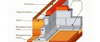
Width of monolithic tape
When making a monolithic reinforced concrete foundation, its dimensions may vary depending on the design conditions, features of the structure and the material used
When making a monolithic reinforced concrete foundation, its dimensions may vary depending on the design conditions, features of the structure and the material used. With the depth of the strip foundation, everything is more or less clear. It can be of two types:
- Shallow. In this case, the bottom mark of the structure is located at a distance of 70 cm or even less from the ground surface. This type of foundation is made for light walls in small buildings.
- The buried foundation is 20-30 cm below the freezing point of the soil. It can be much deeper if the house is being built with a basement or basement.
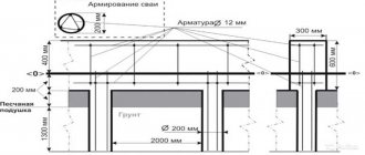
To select the optimal base dimensions, you need to know the following parameters:
- soil composition at the construction site;
- location of groundwater;
- the depth to which the soil freezes in a given region;
- loads on the structure from walls, floor slabs, roofs.
Important: the width of the strip base is selected taking into account the thickness of the walls. It may be slightly larger or slightly smaller than the width of the enclosing load-bearing structures.
If you need to make a base that protrudes forward relative to the plane of the walls, then the width of the foundation can be 5-8 cm larger. To make a base that sinks relative to the surface of the walls, you can use a strip foundation of a smaller width than the walls.
An example of selecting the width of a strip foundation depending on the wall design looks like this:
Reinforcement methods for strip foundations
- If the walls of the building are made of brick, stone or reinforced concrete, then to increase the load-bearing capacity the base is made a little wider. For example, for brick walls whose width is 510 mm, it is better to make a foundation at least 600 mm thick.
- If the walls are laid from light material, for example, logs, foam concrete, or the building is of a frame type, then the size of the foundation can be reduced. So, for walls 50 cm thick, a tape 40-45 cm wide is sufficient.
Important: in any case, the exact dimensions of the strip base can be obtained after an engineering calculation, which can only be done by a specialist, taking into account all design conditions, loads and material characteristics.
TECHNICAL REQUIREMENTS
2.1. Plates should be manufactured in accordance with the requirements of this standard and technological documentation approved in the prescribed manner.
2.2. The slabs must meet the requirements of GOST 13015.0-83:
according to factory readiness;
according to the actual strength of concrete (at design age and tempering age);
on frost resistance of concrete;
on water resistance and water absorption of concrete (for slabs operated under conditions of exposure to an aggressive environment);
to the quality of materials used to prepare concrete;
to concrete, as well as to materials for preparing concrete slabs operated under conditions of exposure to an aggressive environment;
to the quality of welded reinforcement and embedded products;
to steel grades for reinforcing and embedded products, including for mounting hinges;
by deviation of the thickness of the protective layer of concrete to the reinforcement;
on corrosion protection;
on the use of molds for preparing slabs.
2.3. The slabs should be made of heavy concrete (average density more than 2200 to 2500 kg/m3 inclusive) of the compressive strength class indicated in Table. 3.
Table 3
| Slab width, mm | Concrete class based on slab compressive strength for groups based on load-bearing capacity | |||
| 1 | 2 | 3 | 4 | |
| 600 | For group 4 | AT 10 | ||
| 800 | For group 3 | B12.5 | B12.5 | |
| 1000; 1200 | AT 10 | |||
| 1400 | AT 10 | B15 | ||
| 1600 | B12.5 | B15 | B25 | |
| 2000 | B15 | |||
| 2400 | IN 20 | |||
| 2800 | B12.5 | B15 | IN 20 | B25 |
| 3200 | IN 20 | B25 | — | |
2.4. The coefficient of variation in the compressive strength of concrete in a batch for slabs of the highest quality category should not be more than 9%.
2.5. The value of the normalized tempering strength of concrete slabs should be taken equal to 70% of the compressive strength class.
When delivering slabs in the cold season, it is allowed to increase the standardized tempering strength of concrete, but not more than 80% of the compressive strength class. The value of the standardized tempering strength of concrete should be taken according to the design documentation for a specific building or structure.
2.6. The slabs should be reinforced with flat reinforcing blocks assembled from two welded meshes, or with separate welded meshes made of reinforcing steel of the following types and classes:
working reinforcement - rod reinforcing steel of classes A-III and At-IIIC or reinforcing wire of class BP-I;
distribution fittings - reinforcing wire of class BP-I.
2.7. Reinforcing steel must meet the requirements:
rod reinforcing steel class A-III - GOST 5781-82;
rod thermomechanically strengthened reinforcing steel class At-IIIC - GOST 10884-81;
wire class BP-I - GOST 6727-80.
2.8. The mounting loop, embedded in the concrete of the slab, must withstand, during experimental lifting of the slab, a load exceeding the standard force on the loop by three times.
2.9. The reinforcement of the slabs must correspond to that given in Appendix 2.
2.10. The shape and dimensions of reinforcement products (reinforcement blocks, meshes and mounting loops) must correspond to those given in Appendix 3.
The shape and dimensions of embedded products and reinforcement outlets (clause 1.3) and their position in the slabs must correspond to those specified in the design documentation of the building or structure.
2.11. The values of actual deviations of the geometric parameters of the slab should not exceed the limits specified in the table. 4.
Table 4
mm
| Name of deviation of geometric parameter |
Size designation
The applied standard obliges manufacturers of reinforced concrete products to label them in accordance with the provisions of regulatory documents. The slabs are marked with a code consisting of letters and numbers separated by hyphens and periods.
- First, the product labeling (FL) is indicated. Dimensions rounded to the nearest whole number are given in decimeters.
- Then the category of bearing capacity is indicated.
- The last part of the index characterizes the degree of permeability. Additionally, if necessary, design features associated with the presence of embedded elements and reinforcement are indicated.
The product has a special shape, which allows you to significantly reduce the load on the lower blocks and evenly transfer it to the base
In particular, for products used in aggressive environments, the latest permeability index is marked:
- N – normal value;
- P – reduced susceptibility to moisture;
- O – significantly different from reduced (to a lesser extent).
Let's consider the marking FL14.30-2-P. The product has a width of 1.4 m, a length of 2.98 m, and belongs to category 2 in terms of perceived load. The average pressure is 0.25 MPa (2.5 kg/cm²) for a wall with a thickness of 16 cm. Made from concrete with reduced susceptibility to moisture.
Marking is applied to the end or side faces of the reinforced concrete product.
Name of geometric parameter
Prev. off Deviation from the linear dimension Length and width of the slab: up to 1000 ± 10 St. 1000 » 1600 ± 12 » 1600 » 3200 ± 15 Height of the slab ± 10 Dimension that determines the position of the mounting loop on the plane of the slab +10; -5 Dimension that determines the position of the elements of steel embedded products: in the plane of the slab 10 from the plane of the slab 3 Deviation from straightness Straightness of the profile of the upper horizontal surface of the slab in any section over the entire length or width: up to 1000 2.5 St. 1000 » 1600 3.0 » 1600 » 3200 4.02.12. The category of concrete surfaces of the slab is set to A7.
Requirements for the quality of surfaces and appearance of slabs (including requirements for the permissible opening width of technological cracks) - in accordance with GOST 13015.0-83.
ACCEPTANCE RULES
3.1. Acceptance of slabs should be carried out in batches in accordance with the requirements of GOST 13015.1-81 and this standard.
The batch size is determined by agreement between the manufacturer and the consumer, but not more than 200 pieces.
3.2. Acceptance of slabs in terms of frost resistance of concrete, as well as water resistance and water absorption of concrete slabs intended for operation in conditions of exposure to an aggressive environment, should be carried out based on the results of periodic tests.
3.3. Acceptance of slabs in terms of concrete strength (class of concrete in terms of compressive strength, tempering strength), compliance of reinforcement and embedded products, strength of welded joints, accuracy of geometric parameters and thickness of the protective layer of concrete to reinforcement, opening width of shrinkage cracks, category of concrete surface should be carried out according to results of acceptance tests and control.
3.3.1. When accepting slabs based on the accuracy of geometric parameters, the width of the opening of shrinkage cracks and the category of the concrete surface, selective single-stage control should be used.
3.3.2. Acceptance of slabs according to indicators checked by inspection: the presence of embedded parts and mounting loops, the correct application of markings and signs, as well as the presence and quality of anti-corrosion coating should be carried out through continuous inspection with the rejection of structures that have defects according to these indicators.
3.4. Experimental lifting of slabs in order to test the quality of mounting loops and their embedding in concrete should be carried out before the start of mass production of slabs with mounting loops and in the future when the manufacturing technology, type and quality of materials used change.
At least three slabs are tested. After five lifts, upon external inspection of the slab, there should be no signs of local destruction in the area where the loops are sealed.
Choosing the type of foundation for the garage
Arrangement of a garage slab base
Garages are classified as lightweight non-residential premises, but it should be borne in mind that the floor will be subject to additional load from the weight of the machine. Therefore, it is necessary to decide on the choice of the most suitable base option. From the experience of constructing such buildings, the following must be taken into account:
- Building design. Design features include the number of floors, dimensions, height of the walls and materials that will be used in their construction. This determines what the load on the base surface will be. This also includes the functionality of the future garage. Will it be used to repair the car, that is, will it have special performance characteristics?
- Condition of the soil under the garage. Different types of soils also require different design solutions when building the garage itself and, in particular, when laying the foundation.
- The level of water occurrence and the level of freezing, and therefore the impact of frost heaving forces.
CONTROL METHODS
4.1. The compressive strength of concrete should be determined according to GOST 10180-90 on a series of samples made from a concrete mixture of the working composition and stored under the conditions established by GOST 18105-86.
When testing slabs using non-destructive methods, the actual tempering compressive strength of concrete should be determined by the ultrasonic method in accordance with GOST 17624-87 or mechanical devices in accordance with GOST 22690-88, as well as other methods provided for by the standards for concrete testing methods.
4.2. The frost resistance of concrete should be determined according to GOST 10060-87 on a series of samples made from a concrete mixture of the working composition.
4.3. The water resistance of concrete slabs intended for operation in conditions of exposure to an aggressive environment should be determined according to GOST 12730.0-78 and GOST 12730.5-84 on a series of samples made from a concrete mixture of the working composition.
4.4. The water absorption of concrete slabs intended for operation in conditions of exposure to an aggressive environment should be determined according to GOST 12730.0-78 and GOST 12730.3-78 on a series of samples made from a concrete mixture of the working composition.
4.5. Methods of control and testing of welded reinforcement and embedded products - according to GOST 10922-90 and GOST 23858-79.
4.6. Testing of mounting loops and their embedding in concrete is carried out by lifting the slab five times, loaded under the condition of transmitting a force to one loop equal to the standard force on the loop, three times increased, specified in Appendix 3. During testing, the concrete area near the loop in a radius of at least 1, 75 depth of embedding of the loop in concrete should be free from load.
The strength of concrete slabs during experimental lifting should not exceed the tempering strength.
4.7. Methods of control and testing of initial raw materials used for the manufacture of boards must comply with established standards or technical specifications for these materials.
4.8. Dimensions, deviations from straightness of the upper surface of the slabs, the quality of concrete surfaces, the width of the opening of shrinkage cracks and the appearance of the slabs should be checked by the methods established by GOST 13015.0-83.
4.9. The position of reinforcement and embedded products, as well as the thickness of the protective layer of concrete up to the reinforcement should be determined according to GOST 17625-83 and GOST 22904-78. In the absence of the necessary equipment, it is allowed to cut down furrows and expose the slab reinforcement with subsequent sealing of the furrows.
LABELING, TRANSPORTATION AND STORAGE
5.1. Marking of slabs is in accordance with GOST 13015.2-81. Markings and signs should be applied on the side faces of each slab.
5.2. Requirements for the document on the quality of slabs supplied to the consumer are in accordance with GOST 13015.3-81. Additionally, the document on the quality of the slabs must indicate the grade of concrete for frost resistance, and for slabs intended for operation in conditions of exposure to aggressive environments, the water resistance and water absorption of concrete (if these indicators are specified in the order for the production of slabs).
5.3. The slabs should be transported and stored in accordance with the requirements of GOST 13015.4-84 and this standard.
5.3.1. The slabs should be transported and stored horizontally in stacks.
5.3.2. The height of the stack of slabs should not exceed 2 m.
5.3.3. Pads under the slabs and spacers between them in a stack should be placed in the transverse direction (in the direction of width) of the slabs at distances from the ends of the slabs, mm:
750 - with a slab length of 2980 mm;
600 - » » 2380 mm;
300 - » » » 1180 mm;
200 - » » 780 mm.
Installation features
When installing ENIR foundation pads, it is necessary to take into account some points:
- Before laying, leveling should be done using a building level. This will avoid the need to level the foundation.
- It is better to use slabs of the same brand, especially when constructing permanent walls of a construction site.
- It is important to carry out the installation with a dressing. This must be done so that the vertical seams of the rows are not adjacent. To achieve this, blocks of different lengths are used.
A reinforced concrete panel house is installed on foundation pads if a strip base for the house is used. In this case, elements of a certain volume are foundation blocks.
At the same time, GOST states that it is better to install FL exactly the same as building blocks. The procedure consists of the following steps:
- The future site is being prepared for the construction of a house on it and a trench is being dug.
- The entire surface of the dug hole is leveled, and with the help of special equipment the lower plane is compacted.
- Place sand, and crushed stone on top of it and compact it thoroughly.
- After the calculations of the FL and their dimensions are completed, the slabs and blocks are brought to the construction site.
- The slabs are installed using a construction crane, since it is impossible to lift them manually.
- After the assembly is completed, the blocks are reinforced.
- After the foundation pads for FBS are laid, they are bandaged.
- Cover the surface with waterproofing materials to avoid moisture penetration and backfill.
To build a prefabricated foundation, it is necessary to use only those block elements whose dimensions and strength comply with GOST.
ANNEX 1
Mandatory
INSTALLATION DIAGRAMS FOR MOUNTING HINGES IN PLATES
| Slab size | Hinge installation diagram | Dimensions, mm | Loop brand | |
| a1 | a2 | |||
| FL6.24 | I | 200 | M10150 | |
| FL6.12 | II | 590 | M8-100 | |
| FL8.24 | III | M10150 | ||
| FL8.12 | IV | |||
| FL10.30 FL10.24 | III | 300 | 590 | M12-150 |
| FL10.12 | IV | M10-150 | ||
| FL10.8 | 390 | M8-100 | ||
| FL12.30 FL12.24 | III | 400 | 590 | M14-150 M12-150 |
| FL12.12 | IV | M10-150 | ||
| FL12.8 | 390 | M8-100 | ||
| FL14.30 FL14.24 | III | 500 | 590 | M14-150 M12-150 |
| FL14.12 | IV | M10-150 | ||
| FL14.8 | 390 | |||
| FL16.30 | III | M14-150 | ||
| FL16.24 | 600 | 590 | ||
| FL16.12 | IV | M10-150 | ||
| FL16.8 | 390 | |||
| FL20.30 FL20.24 | V | 500 | 590 | M16-200 |
| FL20.12 | VI | M12-150 | ||
| FL20.8 | 390 | M10-150 | ||
| FL24.30 FL24.24 | V | 590 | M16-200 | |
| FL24.12 | VI | M14-150 | ||
| FL24.8 | 700 | 390 | M12-150 | |
| FL28.24 | V | 590 | M16-200 | |
| FL28.12 | ||||
| FL28.8 | VI | 390 | M12-150 | |
| FL32.12 FL32.8 | 900 | 590 390 | M16-200 M12150 | |