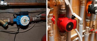
What are the benefits of pump heating systems?
30 years ago, so-called steam heating was common in private homes, where the coolant circulated through pipes and radiators by gravity, and the heat source was a gas boiler or wood stove. Pumps for pumping water were used in district heating networks. When compact circulation pumps for heating appeared, they migrated to private housing construction, as they provided the following advantages:
- The speed of coolant movement has increased. The heat generated by the boiler has become faster delivered to the radiators and transferred to the premises.
- Accordingly, the process of heating the house has accelerated significantly.
- The higher the flow rate, the greater the throughput of the pipe. This means that the same amount of heat can be delivered to rooms through lines of smaller diameter. Simply put, the pipelines have become half the size thanks to the forced circulation of water from the pump, which is cheaper and more practical.
- Highways can now be laid with a minimum slope and water heating circuits can be made as complex and extensive as desired. The main thing is the correct selection of the pumping unit in terms of power and pressure created.
- The household circulation pump for heating has made it possible to organize underfloor heating and more efficient closed systems operating under pressure.
- It was possible to remove from view the ubiquitous pipes that run through the rooms and do not always harmonize with the interior. Increasingly, heating communications are laid in walls, under floor coverings and behind suspended (suspended) ceilings.
Note. A minimum slope of 2-3 mm per 1 m of pipeline is needed to empty the network in case of repair or maintenance. Previously, it was made at least 5 mm / 1 m.p.
Pumping systems also have disadvantages. This is a dependence on electricity and its consumption by the pumping unit during the heating season. Therefore, if there are frequent power outages, the circulation pump must be installed together with an uninterruptible power supply unit or connected to an electric generator. The second drawback is not critical; if you select the power of the device correctly, then the electricity consumption will be acceptable.
Leading manufacturers of heating equipment, such as Grundfos or Wilo, have developed new models of units that can save energy. For example, if you buy and install an Alpfa2 circulation pump from the Grundfos brand, it will automatically change its performance depending on the needs of the heating system. True, its price starts from 120 USD. e.
New generation circulation units from Grundfos – models Alpfa2 and Alpfa2L
Difficulties in installing an additional pump in the heating system
Correct installation of the pump
Having found out whether it is possible to install an additional pump for heating, you need to choose its location correctly
The difficulty lies not in calculating the optimal power, which is also important, but in the consistency of the device’s operation with the main pump
There are several options that will require the installation of additional elements. A special place among them is occupied by the installation of additional heating at home. In practice, this can be implemented in two ways:
- Constructing a separate line with radiators and all the necessary piping. For this you will need an additional boiler;
- Modernization of the existing system - arrangement of a new heating circuit connected to the main one. Then you will definitely need to install an additional heating radiator or several.
The second option is the most practical, since there is no need to purchase additional equipment and components. But then an additional problem arises - asynchronous operation of the pump impellers. Even with the same number of revolutions, this will lead to uneven movement of water in the pipes, which is the first cause of water hammer.
Installation of hydraulic arrow
Water gun with pumps
The way out of this situation is a fundamentally new scheme for installing an additional pump in the heating system. Its innovation lies in the installation of a hydraulic arrow.
This device compensates for pressure drops in a certain area of the system, thereby normalizing the heating operation.
This device normalizes the pressure in the main and return pipes. In additional heating of an apartment, its installation is not necessary, since the increase in the circuit may be insignificant. But if the volume of water in the system increases by more than 20%, means should be provided to normalize circulation and pressure. To install an additional circulation pump in a heating system together with a hydraulic compensator, the following rules should be followed:
- Location - as close as possible to the entrance of the return pipe to the boiler;
- Installation of shut-off valves for each pump circuit;
- Installation of mesh filters.
If it is impossible to install the hydraulic arrow correctly, you can make its simplest analogue. To do this, a through jumper is made after the connection point of the additional pump to the heating system. Its optimal length should be 300-400 mm. This circulation ring will be able to partially balance possible hydraulic shocks.
Double circulation pump
Twin pumps
Is it possible to install an additional heating pump if changing the pipe configuration is physically impossible? There is a more expensive but effective way to improve circulation - installing dual pumps.
This is the best option if you have a gas boiler with a built-in circulation system. The total power of the new pumps should compensate for the forced shutdown of the main one. This way you can avoid malfunctions in the heating system.
The advantages of this modification are as follows:
- There is no need to change the standard installation scheme for an additional pump in the heating system;
- A common connection pipe ensures that there is no uneven movement of water in the pipes;
- Possibility of connecting to a heating control unit - programmer.
Where to install the pump - supply or return
Despite the abundance of information on the Internet, it is quite difficult for the user to understand how to correctly install a heating pump in order to ensure forced circulation of water in the system of their own home. The reason is the inconsistency of this information, which causes constant debate on thematic forums. Most of the so-called specialists claim that the unit is installed only on the return pipeline, citing the following conclusions:
- the coolant temperature in the supply is much higher than in the return, so the pump will not last long;
- The density of hot water in the supply line is less, so it is more difficult to pump;
- The static pressure in the return line is higher, which makes the pump easier to operate.
Interesting fact. Sometimes a person accidentally ends up in a boiler room that provides central heating for apartments, and sees the units there embedded in the return line. After this, he considers this solution to be the only correct one, although he does not know that in other boiler houses centrifugal pumps can also be installed on the supply pipe.
We respond to the above statements point by point:
- Household circulation pumps are designed for a maximum coolant temperature of 110 °C. In a home heating network it rarely rises above 70 degrees, and the boiler will not heat the water more than 90 °C.
- The density of water at 50 degrees is 988 kg/m³, and at 70 °C – 977.8 kg/m³. For a unit that develops a pressure of 4-6 m of water column and is capable of pumping about a ton of coolant in 1 hour, the difference in the density of the transported medium is 10 kg/m³ (the volume of a ten-liter canister) is simply negligible.
- In practice, the difference in static pressure of the coolant in the supply and return lines is equally insignificant.
Hence the simple conclusion: circulation pumps for heating can be installed both in the return and supply pipelines of the heating system of a private house. This factor will not in any way affect the performance of the unit or the heating efficiency of the building.
Boiler room made by our expert Vladimir Sukhorukov. There is convenient access to all equipment, including pumps.
The exception is cheap solid fuel direct combustion boilers that are not equipped with automation. When overheated, the coolant in them boils, since burning wood cannot be extinguished at once. If the circulation pump is installed on the supply side, then the resulting steam mixed with water enters the housing with the impeller. The further process looks like this:
- The impeller of the pumping device is not designed to move gases. Therefore, the performance of the device decreases sharply, and the flow rate of the coolant drops.
- Less cooling water enters the boiler tank, causing overheating to increase and even more steam to be produced.
- An increase in the amount of steam and its entry into the impeller leads to a complete stop of the coolant movement in the system. An emergency situation occurs and, as a result of an increase in pressure, a safety valve is activated, releasing steam directly into the boiler room.
- If no measures are taken to extinguish the firewood, the valve cannot cope with the pressure release and an explosion occurs with the destruction of the boiler shell.
For reference. In cheap heat generators made of thin metal, the response threshold of the safety valve is 2 Bar. In higher quality TT boilers, this threshold is set at 3 Bar.
Practice shows that no more than 5 minutes pass from the start of the overheating process to the valve activation. If you install a circulation pump on the return pipe, then steam will not enter it and the time period before an accident will increase to 20 minutes. That is, installing the unit on the return line will not prevent an explosion, but will delay it, which will give more time to fix the problem. Hence the recommendation: it is better to install pumps for boilers running on wood and coal on the return pipeline.
Basic installation rules
Any equipment is supplied accompanied by the manufacturer’s instructions, which reflect all the important information about its design, operating principle and installation rules. After reading this technical document carefully, you can understand the basic rules for handling it.
When installing it yourself, it is very important to choose the desired position of the product relative to the horizon. The location of the electric motor shaft must be strictly horizontal. Otherwise, air pockets may form, which will leave the bearings without lubrication and sufficient cooling. This will lead to rapid wear of parts and rapid equipment breakdown. There is an arrow on the pump body in the direction in which the coolant in the system should move.
Options for correct and incorrect placement of a circulation pump with a “wet” rotor. It is strictly prohibited to place equipment as shown in the bottom row.
The need for water filtration
A sump tank is installed in front of the pump, the function of which is to filter the coolant. The mud filter traps abrasive particles, sand, scale and other contaminants that get into the water. If such elements get inside the pump, the impeller and bearings may be destroyed. Since the diameter of the insert for mounting the pump is small, you can use an ordinary coarse filter. Please note that the barrel, which serves to collect various suspensions, is directed downward. Being in this position, the filter will not serve as an obstacle to water circulation. When partially filled, the barrel will not lose its ability to pass coolant.
Important! Most filters are equipped with an arrow indicating the correct direction of water flow in the circuit. If you ignore the direction of the arrow, you will have to clean the mud pan much more often.
Pump location in the heating circuit
In principle, most models of modern pumps can work equally well on both supply and return. The equipment can be installed in any part of the heating circuit. It should be taken into account that the duration of operation of the bearings and plastic parts of the device will depend on the temperature of the coolant. Therefore, it is better to install the equipment on the return pipeline after the expansion membrane tank and before the heating boiler.
One of the options for correctly inserting a circulation pump into the pipeline of the heating system of a private house with a circuit length of no more than 80 meters
Why is bypass needed?
The circulation pump is a volatile device. When there is a power outage, the heating system must operate under natural circulation conditions. To do this, it is necessary to minimize resistance in the circuit by reducing the number of bends and turns, as well as using modern ball valves as shut-off valves. When open, the clearance in the ball valve coincides with the diameter of the pipe.
The circulation pump is installed on a bypass, which is cut off from the main system using two ball valves. This placement of the equipment allows it to be repaired or replaced without damaging the heating system of the house. In the off-season, the heating system can operate without a pump, which is shut off using the same ball valves. When frost intensifies, the pump is put into operation by opening the shut-off valves along its edges and closing the ball valve on the main circuit. This is how the direction of coolant flow is adjusted.
Installation of the circulation pump on the bypass (bypass pipe) using three ball valves ensures the coolant flow in the desired direction
Electrical connection
If the heating system is designed on the principle of forced circulation, then in the event of a power outage the pump must continue to operate from a backup power source. Therefore, it is recommended to install an uninterruptible power supply that will allow the heating system to function for a couple of hours. This time is usually enough for specialists to eliminate the cause of an emergency power outage. External batteries connected to a backup power source can extend the battery life of the equipment.
Connecting the pump to an uninterruptible power supply (UPS), which is additionally reinforced by three battery units connected in series into a single circuit
When making electrical connections to the equipment, it is necessary to eliminate the possibility of moisture and condensation getting into the terminal box. A heat-resistant cable is used if the coolant heats up in the heating system by more than 90° C. Contact of the power cable with the walls of pipes, the engine, or the pump housing is not allowed. The power cable is connected to the terminal box from the left or right side, and the plug is rearranged. When the terminal box is located on the side, the cable is inserted only from the bottom. And yes, grounding is required!
The following material will help answer the question of why install a circulation pump:
Pump operating principle
Circulators operate on electricity. There are two approaches to the system, which leads to their division into “dry” and “wet” type devices. The principle of operation of a dry chain is that the drive is completely isolated from each pump and turbine, and rotation is transmitted through the shaft. As a rule, such devices are quite massive.
Dry pumps for circulating water in a heating system are powerful and efficient devices that provide very high flow rates and high pressure in the system. Without them it is difficult to control the heating. They must be installed in an apartment or private house. However, there are some disadvantages:
- The shaft that transmits rotation is a complex sealing system that prevents leakage of liquid under pressure. These seals gradually wear out, requiring regular preventive maintenance, including replacement with new ones.
- The operation of the pump is always accompanied by an air-cooled sound effect.
Finally, the system is a very expensive choice; the best option would be to purchase a wet rotor pump. The vertical wet rotor pump also comes in different types.
Installation rules
There are certain norms and rules that describe at the legislative level where and where it is correct to install the circulation pump. The main part is regulated by SNiP 2.04.05. Almost all rules are based on the operating efficiency and performance of the heating system as a whole, including the pump. For example, the shaft of wet-type equipment must be cut into the pipeline clearly horizontally so that no air pockets appear inside.
A coarse filter must be included in the heating circuit even during the installation of monolithic models. The filtered coolant will cause much less damage to all pump elements than contaminated water.
Certain rules are specified by equipment manufacturers. For example, until relatively recently, some models of the old pump group could only be installed on the return line, since these pumps could not withstand elevated temperatures. Today, pumps are universal in nature and this equipment can be located at any convenient site.
The pump itself can be installed both vertically and horizontally; only when choosing a device you need to make sure that the equipment can operate in both positions. You also need to take into account one nuance: during vertical installation, the power is reduced by approximately 35%. This must be taken into account when choosing a device.
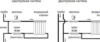
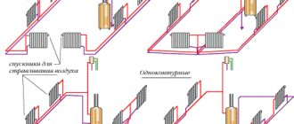
One-pipe and two-pipe systems
Experts distinguish between two heating schemes with forced circulation of the thermal agent - one-pipe and two-pipe. The choice of one or another option determines not only the location of the circuits, but also the length of the pipelines, as well as the type and quantity of equipment for shutdown, regulation and control.
A single-pipe heating system is characterized by the sequential inclusion of heating radiators in the circuit. The coolant returns through a separate pipeline to the boiler only after it turns one by one through all the devices of the system. The disadvantage of this method is that radiators that are closer to the thermal block become warmer than those further away, and this reduces thermal efficiency and equipment life. Introducing a circulation pump into the circuit and equalizing the temperature is achieved at all points of the system.
A two-pipe arrangement has advantages over a single-pipe arrangement, since all heating devices are connected in parallel to the supply and return lines, which promotes uniform temperature distribution throughout all rooms. Forced circulation of the refrigerant leads to increased efficiency of the system and the ability to regulate its thermal power.
Quick installation tips
Among the common options is when the heating circulation pump is installed on a bypass. It is easier to dismantle such a system when the need arises, when the device is temporarily disconnected from the network. The work will require the purchase of the following tools:
- Sealant.
- Tow or linen thread.
- Pliers.
- Assembly is carried out using open-end and adjustable-type wrenches.
Adapters with bends and taps are prepared separately, “American nuts” become part of the original kits. The diameter of the product and reliable material are the most important characteristics that are worth paying attention to.
Actions are performed in the following order:
- Assembling the crane assembly. One is assigned to a straight pipe, the other two are located at the edges of the pump. Precise welding of a fragment with a tap requires preliminary measurement of the “return” section.
- Assemble the pump loop. For now, the nuts are only screwed on, and their tightening is postponed to one of the finishing stages of the work.
- Try on the bypass loop. Separate markings are for places where welding to the pipe takes place.
- Welding. It is better to trust it only to specialists with sufficient qualifications.
- Assemble the lower assembly on the return line.
- Connection of the pump to the power supply.
An arrow is always drawn on the body. It is needed to indicate where the coolant is moving. Preservation of the specified side is ensured when turning the units.
Circulation pumps can be installed both vertically and horizontally. It is important to maintain performance in both directions. In the case of vertical, there is a high probability of a power drop of 30% or more.
The pump is powered from conventional 220-volt networks. It is advised to opt for a conventional connection with a separate power supply line. A phase with zero and protection is required. A three-pin socket with a plug helps organize the connection of elements with each other. If there is a connected power wire, the relevance of the solution increases. Correct installation of the heating pump with your own hands is completed.
Harness
There are two types of heating systems - forced and natural circulation. Systems with forced circulation cannot work without a pump; systems with natural circulation work, but in this mode they have lower heat transfer. However, less heat is still much better than no heat at all, so in areas where electricity is often cut off, the system is designed as hydraulic (with natural circulation), and then a pump is installed into it. This gives high heating efficiency and reliability. It is clear that the installation of a circulation pump in these systems is different.
All heating systems with heated floors are forced - without a pump, the coolant will not pass through such large circuits
Forced circulation
Since a forced circulation heating system without a pump is inoperative, it is installed directly into the gap in the supply or return pipe (of your choice).
Most problems with the circulation pump arise due to the presence of mechanical impurities (sand, other abrasive particles) in the coolant. They can jam the impeller and stop the motor. Therefore, a mesh dirt filter must be placed in front of the unit.
Installing a circulation pump in a forced circulation system
It is also advisable to install ball valves on both sides. They will make it possible to replace or repair the device without draining the coolant from the system. Turn off the taps and remove the unit. Only that part of the water that was directly in this piece of the system is drained.
Natural circulation
The piping of the circulation pump in gravity systems has one significant difference - a bypass is required. This is a jumper that makes the system operational when the pump is not working. One ball shut-off valve is installed on the bypass, which is closed the entire time the pumping is running. In this mode, the system operates as forced.
Installation diagram of a circulation pump in a system with natural circulation
When the electricity goes out or the unit fails, the valve on the jumper is opened, the valve leading to the pump is closed, and the system operates as a gravity system.
Installation features
There is one important point, without which the installation of the circulation pump will require rework: it is necessary to rotate the rotor so that it is directed horizontally. The second point is the direction of flow. There is an arrow on the body indicating which direction the coolant should flow. This is how you turn the unit so that the direction of movement of the coolant is “in the direction of the arrow”.
The pump itself can be installed both horizontally and vertically, just when selecting a model, make sure that it can work in both positions. And one more thing: with a vertical arrangement, the power (pressure created) drops by about 30%. This must be taken into account when choosing a model.
Advantages of a forced circulation heating system
Ardent supporters of heating systems with natural coolant circulation cite a number of seemingly irrefutable arguments in favor of just such a scheme.
- The pump is an extra cost for purchase and installation.
- Any electrical equipment becomes an additional consumer of expensive electricity.
- The dependence of pumping equipment on the stability of the power supply makes the heating system extremely vulnerable in emergency situations in the power grid.
- The pump is an additional component of the system, vulnerable from the point of view of mechanical breakdowns.
It would seem, at first glance, that everything is fair. But if you look at each point impartially, the picture changes literally to the exact opposite.
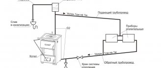
Let's look at the diagram of a heating system with natural circulation:
The simplest diagram of a heating system with natural coolant circulation
Is such a scheme so easy to install and cheap? Not at all!
From the boiler (item 1), it is imperative to install an accelerating vertical section (item 2), from a large diameter pipe - preferably 1½ inches or even more. At the same time, it must reach the highest possible point - above any heat exchange devices. There, at the maximum height, you will have to install an open-type expansion tank (item 3).
The supply manifold (item 4) must be located with a mandatory slope of at least 5% (5 cm for each linear meter of the contour). In this case, again, the diameter of the pipe should not be less than 1¼ inches.
Vertical risers (item 5), through which the coolant is supplied directly to the heating radiators (item 6), are made of pipes with a diameter of at least ¾ inches.
Finally, the requirements for the diameter and compliance with the slope of the “return” collector (item 7) are the same as for the supply pipe. It turns out that in any case the boiler should be located below the lowest radiators.
In a small building with compactly located rooms, this approach is still feasible, and even then not always. Large diameter pipes are not only much more expensive, but also more difficult to install. They are extremely difficult and often impossible to hide without spoiling the interior. The possibility of hidden bottom connections of radiators is almost completely eliminated. The cost of the pump itself and its installation (which can be done independently) is simply not comparable with the costs listed above.
It is impossible to use a hidden arrangement of heating circuit pipes with bottom connections of radiators in a system with natural coolant circulation
Even with the most thoughtful, optimal placement of all elements of a natural circulation circuit, it is unlikely to realistically create excess pressure in it only due to temperature changes and differences in density above 0.6 atmospheres. But such a pressure will clearly not be enough for many modern heating devices. Moreover, you don’t even have to harbor plans to create a water floor heating system.
Moreover, even a minor blockage, somewhere on the bends of pipes or in another area vulnerable to this phenomenon, can completely paralyze the movement of coolant through the pipes. And this will be all the more likely if the system is sufficiently branched, since hydraulic resistance will also have its say.
In order for a system with natural circulation to reach its design capacity, a powerful starting energy “impulse” is required. These are extra energy costs, and quite considerable ones at that. Well, even a short-term shutdown of the boiler for one reason or another will require some effort and a lot of time to bring the heating system back to normal operation. The low speed of the coolant and the consumption of part of the energy generated by the boiler only for its movement is a general decrease in the efficiency of the entire system. And, believe me, these extra energy costs will certainly exceed the total consumption of a compact circulation pump operating with a constant load.
Even relatively inexpensive pumps belonging to energy consumption class “B” consume only about 20÷30 W per hour. And for more advanced class “A” devices this figure is even lower
Low circulation speed also means clearly uneven heating of heat exchange devices installed in such a circuit and distributed throughout the rooms. Adjusting the level of heat transfer from radiators installed in the premises of a house becomes possible solely on a quantitative basis, that is, by changing the volume of liquid passing through the devices. This method is not accurate, and in conditions of low pressure in the pipes it can even lead to blocking of a particular radiator or section of the circuit. To talk about high-quality regulation in such conditions, that is, with the addition of coolant from the return, is generally naive.
You may be interested in information about how heating radiators are installed
The result is the same - the inefficiency of the system directly negatively affects the efficiency of energy consumption, that is, it leads to unnecessary costs during the entire period of heating operation. It’s more profitable to spend money on a pump once...
Finally, a few words about the vulnerability of pumping equipment to the presence of power supply.
This is true, but all electrical appliances in the house are dependent in exactly the same way. Including most modern heating boilers equipped with automation. The problem can be solved - it is enough to install an uninterruptible power supply for the boiler equipment.
If there are power outages in a populated area, the problem is solved by installing an uninterruptible power supply for the boiler and other heating system equipment
With low pump power consumption, even a not-so-expensive and powerful UPS can keep the equipment running for several hours. This is quite enough.
And, finally, nothing prevents you from installing the pump so that in emergency cases it remains possible to switch to natural circulation in the system. This is what they usually do - the pump piping circuit includes a bypass (jumper) and several valves (an automatic valve can also be used).
An example of a circulation pump piping that allows you to quickly switch from forced circulation of coolant to natural circulation and back
Well, about the fact that the pump becomes another vulnerable link in the system. You can reassure the reader: statistics show that failure of circulation pumps relates more to casuistic situations, they are so rare. The designs of devices from leading manufacturers are distinguished by excellent reliability and can last for decades, unless, of course, operating rules are violated. And the resulting benefit in the form of economical operation of the system justifies the purchase of even an expensive pump within two to three years. So from this side there is the least amount of “expecting a catch.”
Selecting a pump installation location
A modern “wet” type circulation pump can be installed in both the return and direct heating branches. Traditionally, the circulation pump is placed in the “return” in front of the boiler in order to:
- Reduce wear and increase the service life of the pump rotor;
- Avoid boiler boiling due to air being drawn out of the boiler by the pump;
- Damage to the pump due to possible boiling of the boiler, especially solid fuel.
Pump diagram in the forward pipeline and Pump diagram in the return pipeline
Features of modern heating systems
A water heating pump is a small device with an electric motor and an impeller that ensures normal coolant circulation in the system. In modern heating it is impossible to do without it - a large number of bends, a small clearance of plastic and metal-plastic pipes, as well as the small capacity of heating devices affect it.
This number of obstacles causes an increase in hydrostatic resistance in the heating system. The abundance of additional elements also has an effect - these are thermostatic valves, manifolds, hydraulic arrows and much more. Many problems are created by the desire to hide all the pipes in the walls so that only the radiators are visible from the outside - in this case, you cannot do without a water pump for heating the house.
Adding fuel to the fire is the complete absence of slopes in modern heating - all pipes are located in a horizontal plane, without deviations in height.
Water pumps are in demand in closed heating systems. Here the coolant flows in a closed circuit without contacting the atmosphere. To install the systems, thin plastic pipes are used, so it is simply impossible to ensure normal flow of coolant here - it is necessary to install a water pump for heating.
The pump can also be installed in an open-type heating system, immediately after the heating boiler, but always before the expansion tank, and not after it.
Instructions for connecting the circulation pump
Note: There are two options for pump tapping: installing a shut-off valve or installing a ball valve on the main tapping line.
- When installing the pump in an existing heating network, first drain all the coolant;
- If necessary, clean the heating pipes;
- A bypass is installed at the pump installation site. The diameter of the bypass pipe must be made smaller than the diameter of the main pipe;
- We install a dirty filter in front of the pump. The filter has an arrow for water movement. It will stop the system sludge;
- The pump shaft must be installed horizontally. An arrow for coolant movement is shown on the pump body;
- Shut-off valves (ball valves) are installed before and after the pump. They play a technical role in case of repairs.;
- A shut-off valve or ball valve is placed on the main coolant pipe;
Criterias of choice
The first important indicator when choosing a pump is its power. For high-quality heating, you should select a device with exactly the power that will be sufficient for heating. More expensive and powerful pumps are not needed for an ordinary residential building - they still will not turn on at full load.
To calculate the optimal power, the following parameters should be taken into account: coolant temperature at the inlet and outlet, pressure, throughput, and productivity of the heating boiler. The coolant consumption can be equated to the boiler power
For example, a heating unit with a power of 30 kW moves 30 liters of coolant in 1 minute
The coolant consumption can be equated to the boiler power. For example, a heating unit with a power of 30 kW moves 30 liters of coolant in 1 minute.
The simplest formula for calculating the optimal pump power looks like this: Q = N/(T2 – T1), in this formula N is the boiler power, and T2 and T1 are the difference in water temperatures at the outlet of the tank and in the return.
The pressure is calculated based on the square footage of the heated area. According to generally accepted standards, a pump power of about 100 W is required per 100 m2 of a residential building.
Installation of the circulation pump is carried out as follows. First you need to carefully study the instructions and the diagram according to which it should be connected. The boiler and all heating equipment require regular inspection and maintenance, so you need to prepare an approach to the main components of the devices in advance. Then you need to drain all the coolant and clean the pipeline, after which you can decide on the installation location.
So, experts recommend installing this equipment near the boiler, on the return pipe. This position is explained by two reasons: a pump installed in this place will allow the coolant to be distributed more evenly in the boiler, and therefore increase the efficiency of the entire heating system. In addition, on the return side the circulation pump will operate at a lower operating temperature, which will increase its service life.
Bypass installation
A bypass (bypass) is performed in the sector selected for installation. This operation is necessary to ensure that the system continues to circulate even if the power supply is turned off or the pumping equipment breaks down.
The diameter of the bypass system pipe must be less than the diameter of the main gas pipeline pipes. Only after installing the bypass do they begin to install the unit.
A drawing with the technology for installing a circulation pump is presented in this diagram:
Installation Features
It must be remembered that the shaft must be positioned horizontally. If installed incorrectly, the circulation pump loses up to 30% of its performance and may fail within a short time. The terminal box must be installed at the top of the system.
Ball valves must be installed on both sides of the unit - they will definitely be needed in the future, during regular technical inspections and scheduled repair work.
The heating system must also have filters to purify the water in the pipelines from various solid particles. The latter, if they get into pumping equipment, lead to serious damage to it.
A valve is installed on top of the bypass pipe to bleed air from the heating system. When installing the motor shaft, it is necessary to provide for the rotation of the box along the axis with a slight force. An expansion tank must be installed in an open heating system.
Correct choice of circulation pump
It makes no sense to buy overly powerful pumping equipment. In addition to the fact that it will not have to work at full capacity, a powerful pump will create negative noise interference. To equip a heating system with complex architecture, accurate calculations must be made by heating engineers. For the owner of a country house to select a pump, a primitive formula is sufficient, since the technical parameters of the installed unit must still exceed the calculated values by 10%.
The ability of the pump to meet the needs of the heating circuit depends on the diameter of the pipeline, the maximum parameters of the pressure and volume of the coolant, the density and temperature of the water.
- The coolant flow rate Q (expressed in l/min) passing through an arbitrary section of a closed circuit is calculated by analogy with the liquid flow rate for a boiler. That is, they simply equate the flow rates and boiler power parameters (P=Q). Simplified: if the boiler power is 20 kW, then 20 liters of coolant per minute can pass through it.
- Batteries with a power of 10 kW will consume 10 l/min of water. Taking into account the power of the radiators, you need to calculate the water flow in each of the rings of the heating network.
- The coolant flow in the pipes depends on the diameter of the pipeline. The narrower they are, the more resistance appears in the path of water movement. With a standard speed of movement through pipes of 1.5 m/sec, the attached table will help in the calculations.
Table for calculating water flow in the pipeline
The pump power is directly proportional to the length of the pipeline. That is, 10 meters of each section of the heating system will require 0.6 m of pressure from the pumping equipment. Simpler: to ensure productive operation of a 100-meter ring, a pump head of 6.0 m is needed.
To stimulate the movement of coolant in heating systems, two types of pumping devices are used:
- “dry” pumps, the rotor of which is not in contact with the coolant;
- “wet” pumps, the working part of which is immersed in the water they pump.
Equipment with a “dry”, hermetically insulated rotor is used mainly for the arrangement of multi-storey buildings, large industrial, shopping and entertainment centers. Due to the noticeable noise effects associated with the air turbulence created during the work process, dry pumps are not in demand in the field of arrangement of private buildings.
Circulation pumps with wet rotor
To modernize the heating of country houses, they mainly use “wet” pumps in brass or bronze cases, inside of which there are parts made of stainless steel and ceramics. The coolant they pump also acts as a lubricant, extending the “life” of the equipment.
Selecting the right unit
When choosing a circulation pump for an autonomous heating system, they are guided by two main criteria - unit performance and pressure. The first of these parameters characterizes the volume of coolant that the unit can pump over a certain period of time, and the second indicates the height to which the pump can lift the liquid. In addition, you need to consider:
- The cross-section of pipes to which the circulation pump will be connected.
- Dimensions of the space allocated for installation of the pumping unit.
- Maximum coolant temperature.
- Power and throughput of the heat generator.
- Volume of heated premises.
We have already talked about the classical calculation method in the article Calculation of a circulation pump for heating in examples and formulas. At the same time, there is a simpler method that can be used both for preliminary calculations and for checking the results of more thorough calculations. It is based on the requirement that the circulation pump must pump three times its filling volume through the heating system in one hour of operation.
The last value can be indirectly estimated from the power characteristics of the boiler. If the thermal unit was selected according to the rules, then for every kilowatt taken from its technical data sheet there are at least 15 liters of coolant. It is enough to multiply the power of the heat generator in kW by 15 and make a correction of 20% in order to estimate the filling of the heating circuits with sufficient accuracy. After the volume of coolant has been calculated, it will not be difficult to calculate the required performance of the circulation pump in l/min - to do this, the filling of the circuits in liters must be multiplied by three and divided by sixty. If we take a heating system with a 15 kW boiler as an example, we can assume that the volume of liquid in all its branches is approximately 270 liters (Q = 15 kW x 15 l + 20%). For forced circulation of coolant, you will need a pump with a flow rate of at least 0.81 m3/hour or 13.5 l/min.
The required pressure value of the circulation pump can also be determined without going into complex mathematical calculations. To do this, you can use the formula N = X * K, where X is the number of floors of the building, including the basement, and K is a correction factor equal to 0.7-1.1 for traditional two-pipe heating schemes and 1.2-1.85 for collector-radial circuits. So, if you calculate the hydraulic resistance of a collector heating system of a two-story building with a basement (the number of levels is three), then you will need a pump with a pressure of 3x1.85 = 5.55 m.
The obtained values will already be enough to decide on a specific model of a circulation pump from any manufacturer. To do this, the operating point is found on the graphs of the hydraulic characteristics of centrifugal units - it is located at the intersection of the segments drawn from the abscissa (performance) and ordinate (pressure) axis. The best position of the operating point is considered to be the middle third of the graph, which corresponds to the maximum efficiency.
The graph of the hydraulic characteristics of the circulation pump allows you to analyze whether the unit meets the requirements for pressure and performance
To obtain a sufficient reserve in both directions, you should focus on the curve constructed for the average speed of the circulation pump. In this case, it will be possible to reduce its power if there is excessive noise or increase it if the coolant at the entrance to the boiler has an unacceptably low temperature.
Features of the design of a heating system with pump circulation are studied in this article:
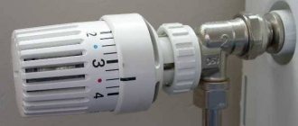
Thermal valves installed in many heating systems regulate the room temperature in accordance with the specified parameters. The valve closes when the temperature rises. This increases hydraulic resistance and, accordingly, increases pressure. These processes are accompanied by the appearance of noise, which can be eliminated by switching the pump to low speed. Pumps with built-in electronics that can smoothly regulate pressure drops depending on changes in the amount of water cope with this task more effectively.
Read more about how to choose such a pump in the articles: Selecting a circulation pump for heating.
Pump characteristics
All circulation pumps have two main parameters:
- N – pressure value, i.e. the height to which the pump can lift liquid (measured in meters);
- Q is the fluid consumption over a certain time period (measured in cubic meters), which is directly dependent on the power of the heating boiler and the diameter of the pipes used.
The pump in the heating system is practically not used to lift water, so the main indicator is the Q parameter. Modern heating boilers often have a built-in pump, so installing an additional pump is not required.
The need to install a circulation pump arises if a weak boiler is used, or if the heated area has been increased. Before installing an additional pump in the heating system, you need to calculate the fluid flow in the circuit. In addition, you need to correctly select the pump power, which is determined depending on the length of the pipeline - every 10 m of circuit length requires 0.6 m of pressure.
There are two main types of pumping equipment:
- Dry
. In such devices, the pumped liquid does not come into contact with the rotor. Tightness is achieved by a seal located between the pump and its motor. The efficiency of dry pumps is about 80%, which allows them to be successfully used for pumping large volumes of liquid. Pumps of this type are not used for home heating systems due to the excessive noise level they generate during operation. - Wet
. In this case, the rotor is immersed in the pumped coolant. The engine is cooled using water. Electricity is supplied to the device through the stator. Among the advantages of such equipment, it is worth noting durability, reliability, compactness, ease of maintenance and low noise level. The main disadvantages are low efficiency (no more than 50%), the ability to use such devices only in private houses and apartments, as well as the complete unsuitability of wet pumps for pumping drinking water.
Installation of additional equipment and its connection
Typically, closed or open radiator systems with one boiler are equipped with one circulation pump. More complex schemes require additional water pumping devices.
We are talking about such cases:
- A private house is heated by more than one boiler system.
- The boiler piping does not have a buffer tank.
- The heating circuit includes several branches for servicing various devices - radiators, heated floors, indirect heating boiler, etc.
- If a hydraulic separator is used.
- Water supply for heated floors is organized.
In order to properly connect several boilers operating on different types of fuel, you will need to provide each of them with a separate pump. A system with a buffer tank requires a heating circuit with two pumps, because We are talking about at least two circulation circuits - boiler and heating.
Highly complex heating schemes with several circuits deserve special mention: they are usually used in large cottages with 2-4 floors. In this case, you may need from 3 to 8 pumps to supply coolant to each floor and to different heating devices. A heating circuit with two pumps is used in cases where the house has two water floors. In some cases, connecting a pump to the heating system of a private house is not required at all, because Most electric and gas wall-mounted boilers have their own pumping devices.
About the choice of equipment and the rules for its independent calculation
The key indicator that determines the efficiency of the circulation pump is its power. For a household heating system, there is no need to try to purchase the highest-power installation. It will only make a loud noise and waste electricity.
Mounted circulation pump
You need to correctly calculate the power of the unit based on the following data:
- hot water pressure indicator;
- pipe section;
- productivity and throughput of the heating boiler;
- coolant temperature.
Hot water consumption is determined simply. It is equal to the power indicator of the heating unit. If, for example, you have a 20 kW gas boiler, no more than 20 liters of water will be consumed per hour. The pressure of the circulation unit for the heating system for every 10 m of pipes is about 50 cm. The longer the pipeline, the more powerful the pump you need to purchase. Here you should immediately pay attention to the thickness of the pipe products. The resistance to water movement in the system will be stronger if you install pipes with a small cross-section.
In pipelines with a diameter of half an inch, the coolant flow rate is 5.7 liters per minute at the generally accepted (1.5 m/s) speed of water movement, with a diameter of 1 inch - 30 liters. But for pipes with a cross-section of 2 inches, the flow rate will already be at the level of 170 liters. Always select the diameter of the pipes in such a way that you do not have to overpay extra money for energy resources.
The flow rate of the pump itself is determined by the following ratio: N/t2-t1. In this formula, t1 refers to the temperature of the water in the return pipes (usually it is 65–70 °C), and t2 is the temperature provided by the heating unit (at least 90 °C). And the letter N denotes the boiler power (this value is in the equipment passport). The pump pressure is set according to the standards accepted in our country and Europe. It is believed that 1 kW of power of a circulation unit is quite enough for high-quality heating of 1 square meter of a private home.
Water pump for heating a private house: consider the options
When resolving issues with organizing the heating of their own homes, the vast majority of homeowners give preference to a water heating system. Methods for obtaining heat may vary - depending on the availability of energy sources, the types of fuel prevailing in the region, and the cost-effectiveness of one or another approach. That is, in fact, the boiler can be installed depending on the circumstances, gas, electric, solid fuel - long-burning or with automatic fuel supply, diesel, etc. But the distribution of thermal energy throughout the premises in most cases is carried out by means of a coolant circulating through the pipe circuits - water or a specially selected technical fluid.
Water pump for heating
When designing a water heating system, independently or with the involvement of specialists, it is necessary to competently approach the selection of all units, components and components, from the boiler and radiators to pipes and the last valve - everything must fully comply with the planned parameters of the system being created. A water pump for heating also plays one of the key roles, since a system equipped with a device for forced circulation is always characterized by stable operation and high efficiency. Therefore, this publication will be entirely devoted to the nuances of pump design, criteria for their selection and basic installation rules.
Is a water circulation pump really necessary for heating?
Surely, many of the thrifty owners will wonder whether it is possible not to “bother” with the pump at all. Indeed, in a small house with slightly branched circuits, heating can be organized according to a natural circulation scheme.
Yes, of course, there is such a possibility. To do this, it is necessary to correctly position the expansion tank, select pipes of the appropriate diameter and mount them with a certain slope, and optimally position the heating radiators. In a word, when they talk about the simplicity of a system with natural circulation, this statement is very doubtful.
The main advantage of natural circulation is that it is not tied to electrical power (unless, of course, the boiler itself is energy-independent). In all other respects, it is significantly inferior to forced circulation.
The simplest diagram of a heating system with natural circulation
Thermal engineering calculations show that even under the most optimal conditions - high boiler efficiency, rational placement of all components, clean pipes not overgrown with sediment and a minimum of shut-off or other fittings, the natural increase in pressure due to the temperature difference and the creation of a slope will be within 0. 6 atmospheres. This is clearly not enough to overcome strong hydraulic resistance in an extensive network or even in the event of force majeure circumstances - a blockage in the pipes with a narrowing of the internal clearance or even a short-term stop of the gas boiler can lead to an imbalance in the heating system, and it will take a long time to “bring it back to life” "
So, let’s summarize the advantages and disadvantages of natural and forced circulation:
1. The advantages of natural circulation, as already mentioned, include complete energy independence and the relative simplicity of piping the boiler itself. But there is a whole list of shortcomings:
— The need to use pipes of different, including fairly large diameters, which leads to increased costs of the project and difficulties in installation. The system requires very careful thermal calculations, with precise adherence to slopes, with mandatory consideration of the excess of the location of some elements over others and with other nuances.
— Transfer of thermal energy over significant distances (heights) is simply impossible. Both the height and length of the created outline are limited.
— The low speed of natural movement of the coolant leads to completely unnecessary energy losses, uneven heat distribution throughout the rooms, and therefore to a decrease in the overall efficiency of the system and its efficiency.
— A system with natural circulation is very difficult to make any precise adjustments or optimize the distribution of heat flows throughout the premises of the house.
2. And now - about forced circulation in heating circuits.
Its disadvantages include dependence on the availability of power supply - if there is a power failure, the heating system stops.
- Well, firstly, nothing prevents you from organizing the entire system in such a way that it can operate in both modes - it is enough to install the pump unit on the “return” in front of the entrance to the boiler. For example, the figure reproduces the same diagram, but indicating the insertion location of the circulation pump. The strapping procedure will be described below.
The same circuit, but with a circulation pump added to it
“Secondly, let’s agree that now is not the “dawn of the country’s electrification.” And, hand on heart, let’s give ourselves an honest answer to the question - how often, how regularly and for what duration is electricity cut off in a particular area (city, village). If these are just annoying episodes associated with some emergency situations, then everything can be solved by installing an uninterruptible power supply system. The power consumption of circulation pumps is usually very small, and even a small UPS will easily keep the entire heating system in working order.
If, of course, there are still places where power outages are systematic and long-lasting, then in these populated areas it is certainly better to organize heating according to a natural circulation scheme.
But installing pumping equipment at once gives the heating system many advantages:
- The material consumption of the created system is sharply reduced - large-diameter pipes may not be needed. And this also makes the installation process easier.
- Subject to the necessary thermal insulation measures for pipelines, thermal energy can be transmitted over significant distances and heights, which is very important for a heating system in large cottages, on several floors or with extensions.
- The efficiency of the heating system increases sharply. The energy costs of operating the pump cannot be compared with the gains achieved by increasing the efficiency of the system.
- It becomes possible to “zoning” the heating system, using various heat exchange options – conventional radiators, convectors or water-heated floors.
- The heating system turns out to be “flexible” - it can be easily adjusted both in general and in its individual sections. In any room, if desired, you can maintain an individual heating level. If necessary, you can quickly organize heat redistribution with an emphasis on a specific area.
- A forced circulation system is much easier to start up and regular maintenance.
Probably, no more convincing is needed: inserting a circulation pump into a water heating system can be considered an urgent necessity. If it is not yet installed, then during the next maintenance of heating with natural circulation or during its reconstruction, this issue should be placed as a priority.
And now closer to the issues of designing pumps and choosing the right models.
How are circulation pumps designed?
Almost all circulation pumps are organized according to a centrifugal design. In a special chamber (snail), a paddle wheel (impeller) rotates, which throws the incoming fluid flow from the center to the edges of the chamber. Due to the centrifugal force, when the wheel rotates, an area of rarefaction is created in the center at the inlet, and an increased pressure at the outlet. This difference is enough to create an even, stable circulation flow in the heating circuit.
The main problem that faced the developers of pumps of this type was to ensure reliable insulation of the electrical part. The first bold attempts were made at the beginning of the 20th century, when the first circulation pumps with a rotor completely isolated from water (dry type) were created. Somewhat later, installations with rotors located in a coolant medium (wet type) were developed.
Of course, since then the designs have been constantly improved, but to this day the same operation schemes of circulation pumps are used - “dry” and “wet”.
Dry-type pumps are usually quite massive and require cantilever installation
1. “Dry” type pumps are usually massive, with a characteristic elongated engine compartment placed to the side. They are quite noisy, and installation in residential premises is impractical from this point of view.
An approximate design of dry pumps is shown in the figure (the area filled with coolant is indicated in green):
Approximate diagram of a dry type pump
An electric motor (item 2), which requires cooling during its operation, therefore most often a casing (item 1) is installed on it, under which a fan is hidden.
The motor rotor shaft is mounted on a ball bearing (pos. 6), and the internal part of the electric motor is additionally protected (pos. 7) by an o-ring (sometimes a gland-type seal).
The electric motor block is connected to the pump housing (pos. 9) through a metal (cast iron, brass) support flange (pos. 3) with bolts or screws. The gasket (item) ensures the tightness of this interface.
The working shaft sleeve (item 5) contains a pair of sealing rings (item 11), made of a special material that ensures their tightest fit to each other due to the difference in external atmospheric pressure and the pressure created by the pump. Rings are made from a special carbon agglomerate, ceramic or, less commonly, stainless steel.
The creation of pressure is ensured by the rotation of the impeller (pos. 12), which throws the liquid coming from the entry point into the chamber (pos. 10) to the edges of the “snail”.
To prevent air accumulation, an air valve is provided (item 4). It is often possible to install a control pressure gauge at the outlet - the figure shows a plugged hole for it (item 13).
Dry-type pumps are characterized by high performance, their efficiency reaches 80%. But, at the same time, they require much more attention - the sealing rings must be periodically replaced, as they wear out quite quickly. Typically, such pumps are installed in separate rooms due to their noise and the need for special conditions. The usual scope of their application is powerful substations or heating systems, where the performance of pumping equipment plays a decisive role. In home systems they are used in exceptional cases - here pumps with a “wet rotor” are quite sufficient.
2. “Wet” type pumps are always much more compact (with equal indicators, pumps most often require cantilever installation, while “wet” ones simply crash into the pipeline.
“Classic” type of circulation pump with a “wet” rotor
They do not require an additional cooling system - excess heat is always removed by the liquid circulating through them.
The design of a “wet” circulation pump can be schematically depicted as follows:
Diagram of a pump with a “wet” rotor
The motor stator (pos. 4) in this case is located in a sealed metal “glass” (pos. 8). The rotor does not have the commutator-brush mechanism usual for an engine; electrically it is organized differently, since it rotates in a liquid coolant medium (shown in the same way as in the first diagram with a greenish background). The rotor shaft (pos. 7) rests on both sides on bearing bushings (pos. 2), and the coolant itself in this scheme acts as a never-drying lubricant. That is why it is very important that air does not accumulate inside the pump and that the bearings are always in a “wet” state. To achieve this, the motor shaft must remain exclusively horizontal in any position of the pump, and a threaded valve plug (item 6) is provided to release air, the sealing of which, when screwed, is ensured by a gasket (item 5)
Otherwise, there is the same “snail” chamber in a cast iron or brass body (item 1), an impeller (item 3), which creates centrifugal acceleration of the liquid and a pressure difference at the inlet and outlet of the pump.
Advantage - no need for complex and wear-out seals on rotating units. Conventional gaskets on fixed joints (item 10) completely solve the problem of sealing the pump.
The rotor rotates in a liquid medium, which, of course, due to the increased resistance of water, significantly reduces the efficiency of such a pump (usually this figure reaches approximately 50%). However, the use of a “wet” pump is quite justified in the conditions of an individual heating system:
- Such pumps operate almost silently - even when installed in residential premises (for example, on a “warm floor” collector), they do not cause any discomfort.
- Low efficiency is fully compensated by low energy consumption. Thus, pumps of the initial performance category, which are most often used for heating systems of small houses and cottages, have a rated power consumption of 25 to 50 W - comparable to a small light bulb.
- If operating requirements are met, they can serve for decades, absolutely without requiring any intervention - preventive maintenance or repairs. The main thing is not to leave the rotor dry. Otherwise, by and large, there is simply nothing to break or wear out (unlike commutator electric motors, whose brushes wear out, or a “dry” pump circuit, with sealing rings that gradually wear out).
So, there is no need to be too clever - for home autonomous heating systems, pumps with a “wet” rotor will be sufficient.
They are also convenient because they have a modular design - they can be easily disassembled into component units, each of which, in case of failure, can be replaced with a working one.
As a rule, such pumps have a modular design
In the figure the numbers indicate:
1 – housing of the pump working chamber. Most often it is made of gray cast iron, although there are also models made of copper alloys (brass or bronze).
2 – impeller. It experiences significant loads from fluid resistance, so it is made of durable polymer composites with fiberglass reinforcement.
3 – rotor of the electric drive of the pump with permanent magnets.
4 – working axis (shaft) of the rotor. In modern pump models, they are made of high-strength cermets. On the impeller side it rests on a radial bearing in a stainless steel bearing cage. On the opposite side (engine side) - into the support bearing. Both locations feature durable plain bearings made from a combination of graphite and ceramic.
5 – pump electric drive stator housing. It can be cast iron or stamped stainless steel.
6 – terminal box where the power cable is connected. The pump operating mode regulator is also usually located on it (if provided for by the design).
7 – valve (air screw) for bleeding air from the pump housing after filling the heating system.
The assembly of all modules into one structure is carried out using a screw connection and is absolutely not difficult.
Video: design and installation of the Grundfos circulation pump
How to choose the right circulation pump?
Now that a certain clarity has been achieved with the design of the circulation pump, you need to understand the parameters for selecting this device for a specific heating system.
Despite their external similarity, pumps can differ significantly in operating parameters
Externally, such pumps, especially from the same manufacturer, can be very similar to each other, and even differ slightly in size or color. However, there are differences between them and this must be taken into account when choosing. What are the main criteria when choosing?
- Supply voltage - usually at home, equipment with a single-phase power supply of 220 V, AC frequency of 50 Hz is used.
- Power consumption depends on the specific model and operating mode. Pumps that can be switched to several speeds of pumping water usually have a sign on the body indicating the power consumption and current in each mode. However, for almost all pumps used in everyday life, the maximum load power rarely exceeds 50 - 70 W.
Some parameters are often indicated on the pump body
- The maximum temperature of the pumped liquid must be taken into account. For pumps designed for heating systems, as a rule, the permissible maximum is 110 degrees, that is, with a huge margin, more than enough.
- Of the dimensional values, the diameter of the threaded part and the installation length are primarily of interest. The vast majority of pumps are cut into the circuit using American union nuts (flanged) nozzles with the nuts themselves are often included in the delivery package of the pump. The diameters most commonly used in private housing according to the European metric classification are 25 or 32 mm (1 and 1¼ inches). Standard installation lengths for pumps of this class are 130 or 180 mm.
- Protection class for electrical appliances - as a rule, modern circulation pumps have a protection class of IP44 according to the international classification. This means that the devices are protected from the ingress of solid foreign objects and particles larger than 1 mm (the first digit is “4”), and are also fully protected from water splashes or drops flying at any angle hitting the electrical contacts (the second digit is “4”) ").
- The maximum outlet pressure is often indicated on the pump body (usually about 10 bar). In practical application, this value does not mean much. Much more important are related indicators - the performance of the device and the created water pressure.
- Pump performance is the amount of liquid that it is capable of pumping per unit time. Typically this value is indicated in m³/hour.
- The amount of pressure created is measured in meters (decimeters) of water column.
- Very often, the main technical parameters of pumps are included in their factory model name. For example, the name of a Danish pump will tell you that this is a product from the “Alpha2 L” model line, both pipes at the inlet and outlet have a diameter of 25 mm, the created water pressure is 40 dm (4 m), and the installation length of the pump is 180 mm.
It’s not difficult to figure this all out, but how can you determine which model is best suited for a specific heating system? Here it’s a little more complicated, since you’ll have to go deeper into the calculations.
Independent calculation of pump parameters
The easiest way in this case is to take the average value using the table. However, it would be appropriate to make a number of warnings:
This table is calculated for almost ideal conditions - the highest efficiency of the boiler and pump, the optimal ratio of the volume of coolant in the system to a unit of power (10 ÷ 12 l/1 kW). For the calculations, the condition of three complete circulation of the coolant within an hour was taken.
Prices for electric water pumps Gilex
Pump GILEX Compass
Please note that in the heating boiler power columns three values are indicated - for conventional radiator heating with a temperature difference at the inlet and outlet ΔT=20 °C, for a convection circuit - ΔT=15 °C, and for a “warm floor” system, in which The temperature difference is always ensured to be minimal - ΔT=10 °C. (The full table is not given - here is only an excerpt from it for a heated area of up to 1100 m²).
| planned heating area (sq. m) | Required thermal power (kW) with temperature differences of the coolant at the inlet and outlet of the boiler (Δt) | pump parameters (minimum) | |||
| Δt= 20° | Δt= 15° | Δt= 10° | productivity (m³/hour) | created pressure (without taking into account hydraulic resistance and branching of the system) | |
| up to 200 | 28,0 | 21,0 | 14,0 | 1,25 | 1,0 |
| 350 | 46,0 | 35,0 | 23,0 | 2,0 | 2,0 |
| 500 | 70,0 | 52,0 | 35,0 | 3,0 | 2,0 |
| 900 | 116,0 | 87,0 | 58,0 | 5,0 | 3,0 |
| 1100 | 140,0 | 105,0 | 70,0 | 7,0 | 3,0 |
However, not all so simple. Of course, the data obtained can, to a certain extent, become a guideline for purchasing the desired model, but you can still make a mistake, since the obtained values do not take into account, for example, the features of the hydraulic resistance of the heating system and its branching. And the resistance values (pressure loss created by the pump) can be quite significant:
| Heating system elements | Approximate pressure loss across elements (kPa) |
| Standard heating boiler | up to 5 |
| Compact heating boiler | from 5 to 15 |
| Autonomous heat exchanger (if there is a dual-circuit system) | from 10 to 20 |
| Calorimeter (thermal energy meter) | from 15 to 20 |
| Indirect heating boiler heat exchanger | from 2 to 10 |
| Body pump | from 10 to 20 |
| Radiator | up to 1 |
| Heating convector | from 2 to 15 |
| Radiator valve | to 10 |
| Three way valve | from 10 to 20 |
| Check valve | from 5 to 10 |
| Coarse filter (with clean mesh) | from 15 to 20 |
| Hydraulic resistance of plastic pipes | 150 Pa per 1 running meter |
So it’s better to take a house (apartment) plan, a piece of paper, a pen, a calculator, and calculate all the parameters yourself. It's not that difficult and won't take much time.
1. To begin with, we will determine the required thermal power to heat the rooms that will be covered by our heating system. To do this, we sum up the area of all rooms, obtaining the value Σso.
2. Using the table of specific capacities (Qs), we determine the required value based on the region of residence:
| Region of Russia in which construction is taking place | Specific power value Qs (kW) per 10 m² |
| Southern regions of the country (North Caucasus, Caspian, Azov, Black Sea regions) | 0,7 ÷ 0,9 |
| Central Black Earth Region, Southern Volga Region | 1,0 ÷ 1,2 |
| Central regions of the European part, Primorye | 1,2 ÷ 1,5 |
| Northern regions of the European part, Urals, Siberia | 1,6 ÷ 2,0 |
3. Substitute the data into the formula M = Σ so × Qs: 10
For example, it is necessary to carry out calculations for a house located in the Ryazan region (Central region). The total area of the cottage covered by the heating system is 200 m².
M = 200 × 1.3 / 10 = 26 kW.
4. Pump performance is calculated using the following formula:
G = M / ΔT × St
M is the required boiler power, the power that we have already found earlier (in W).
ΔТ – temperature difference in the heating system, which was mentioned above – 20, 15 or 10 degrees.
St is a coefficient that takes into account the specific heat capacity of the liquid used as a coolant. For water, this value is taken to be 1.16. If another liquid is poured into the system, for example, antifreeze with appropriate additives, then this value must be indicated in its characteristics.
In our case, we consider for conventional radiators and for water as a coolant
G = 26000 / 20 × 1.16 = 1121
The resulting value is expressed in kilograms per hour, which, you see, is not entirely convenient. But there is nothing easier than converting it into units of volume - simply divide it by the density of water at an average temperature of about 70 degrees -970 kg/m³.
As a result, we get G = 1121 / 970 = 1.21 m³/hour
The same calculation, but much faster, can be done using the proposed calculator:
Calculator for calculating pump performance
Go to calculations
5. The next most important quantity for the correct selection of a pump is the water pressure it creates (often called the water column).
The main point here is that the pump must create a force that overcomes the hydraulic resistance in all parts of the system. In this case, the vertical rise of the coolant is not particularly taken into account, since this is fully compensated by the reversely directed force on the descending sections of the circuit. But the resistance of pipes, valves, heat exchangers, and other elements is very important.
As the reader has already seen from the table above, each element of the heating system gives a certain pressure drop. Intellectually, of course, it is necessary to carry out a full detailed calculation - by the way, this is exactly what is done when using special application programs. However, practice shows that in conditions of limited systems, on the scale of a house or apartment, it is enough to take into account the length of the pipes, and then enter a correction factor for “complexity” into the formula.
The formula looks like this:
Н = Σᴸ × R × Zr
N – calculated pressure created by the pump (the value will be obtained in pascals, Pa)
Σᴸ is the total length of the entire heating circuit, including both supply and return pipes. If a water heated floor is provided, then the full length of all circuits connected to one pump must be taken into account.
R is the resistivity of a meter section of pipe. We look at the table - for plastic pipes this value is 150 Pa/m
Zr is a coefficient that takes into account the saturation of the system with shut-off valves, fittings, thermostats, heat exchangers, etc. – all those elements that create pressure losses. The value of this coefficient is taken equal to:
1.3 – if standard, standard fittings and valves are used.
1.7 – when using thermostatic elements in the system (three- or four-way valves that maintain a set temperature level).
2.2 – with a highly branched system, with a large number of shaped and regulatory elements.
Let's say we calculate the required pressure for a system with a total pipe length of 170 m, and with thermostats installed on each of the heating radiators. In this case, it is better to take the coefficient 2.2
H = 170 × 150 × 2.2 = 56100 Pa
To convert to meters of water column (approximately, but with an acceptable level of accuracy), you need to divide by 10,000. As a result, we get 5.6 meters.
So, in the example we are considering, we decide on the choice of pump - the minimum productivity is 1.23, rounded to 2 m³/hour with a created pressure of 5.6 - rounded to 6 m.
Calculator for calculating the pressure created by the pump
Go to calculations
Excessively overestimating the parameters of the purchased equipment is absolutely pointless. Even the above formulas already contain a certain reserve, which should be enough for all “force majeure”. Excessive productivity and pressure will simply remain unclaimed and will even create a certain imbalance in the operation of the heating system, leading to unnecessary waste of electricity.
Some tips for installing a circulation pump
Installing a pump in a heating system usually does not cause much difficulty, especially when using polypropylene pipes. This requires few tools and components.
A typical set of tools and accessories for installing a circulation pump
Selecting and welding American nuts into the contour at a distance corresponding to the installation length of the device is not a difficult task for an experienced home craftsman. And then all that remains is to install the pump itself, put on the sealing gaskets and tighten the American ones on both sides.
After the couplings with union nuts are cut into the pipes, installing the pump itself is a matter of one minute
However, when installing a pump, we must not forget about a number of nuances.
- Wherever the pump is installed, it is recommended to install a mesh (“oblique”) filter in front of it in the direction of flow of the coolant. The entry of solid particles into “wet” pump bearings can damage them or reduce the efficiency of the device.
- It is recommended to install a check valve after the pump - this measure is aimed at preventing reverse flow when the pump power is turned off and to protect against possible water hammer
- In conventional radiator or convector heating systems, it is recommended to install the circulation pump at the point with the lowest temperature - on the return line in close proximity to the boiler.
Typical pump installation location in radiator heating systems
- If a “warm floor” system is organized, then the pump, on the contrary, is installed only on the supply side. Temperature differences here are small, but the danger of airing the circuits is quite serious. To avoid the possibility of a flow break, the pump is placed in front of the supply manifold.
- To ensure the ability to switch the system from forced to natural coolant circulation, the pump can be mounted according to the following scheme:
Recommended installation diagram for the circulation pump
: The pump itself (item 1) is mounted on standard American union nuts (item 5).
— As already mentioned, a coarse mesh filter (item 3) is installed in front of the pump, and a water return valve (item 4) is installed directly behind it.
— These units are controlled using three valves (item 2). Either a straight section is left open - for natural circulation, or vice versa - a section with a pump. By the way, the valve in the direct section can also be used for fine balancing of the system when the pump is running - in this case it plays the role of a kind of bypass.
- This has already been mentioned, but it would be useful to remind you that pumps with a “wet” operating principle are installed only in a position that ensures the rotor is strictly horizontal.
- A power outlet must be provided near the pump installation site so that the cord is long enough without tension. In most cases, pumps require an outlet with a mandatory grounding circuit.
When installing the pump, do not forget about the need to properly connect it to the power supply network
- After installing the pump, under no circumstances should it be turned on until the system is completely filled with coolant - even short-term idling can damage the device.
- Before filling and starting the system, it is advisable to rinse it thoroughly with clean water so that no solid inclusions remain in the pipe cavities.
- Despite the IP44 degree of protection, the possibility of splashing water on the terminal box should still be completely excluded.
- If the pump is equipped with an air valve, be sure to check for air before starting and release it. The presence of air pockets for pump operation is unacceptable.
- If the pump has several operating modes, then the optimal one is selected, which corresponds to the maximum extent to the system parameters. The load should not be overestimated - this has already been said.
In this regard, modern circulation pumps are especially convenient, they are equipped with an electronic unit for monitoring and adjusting the pressure created in the system, which constantly maintains the required parameters depending on the presets made in advance.
An example of a modern electronically controlled circulation pump
And finally, one last piece of advice. When choosing, you should not take pumps from unknown manufacturers. Such a purchase is made for a long time, and it is better to purchase a really high-quality device that will last for many years without any interference in its operation. So, without fear, you can purchase branded products from European companies, “Grundfos”, “Wilo”, “Pedrollo”, “DAB”, “Ebara”. Among Russian products, we can highlight pumps under the brand name “Jeelex”.
Prices for popular water pumps
Video: how to distinguish real Grundfos from a fake
The cost of even the highest quality pumps is not so high as to resort to completely unjustified “penny savings” in this matter - all this can result in much more unpleasant consequences.
Do-it-yourself pumping equipment installation diagrams and standards
Circulation pumps are installed in two ways. The first connection diagram for the unit is two-pipe. This connection method is described by a high temperature difference in the system and variable coolant flow. The second scheme is one-pipe. In this case, the temperature difference in the heating system will be insignificant, and the media consumption will be constant.
Installed circulation pump
Connect the pump yourself according to the instructions that come with the unit. It also indicates the installation procedure for the functional reinforcement chain. Before installing the pump, be sure to drain all water from the system. Often there is a need to clean it. During the operation of the heating boiler, a lot of debris accumulates on the internal surfaces of the pipes, which worsens the technical performance of the system.
Experts advise placing the circulation unit in front of the boiler - on the return line. This is done in order to eliminate the risk of boiling of an open type heating system due to the vacuum that is created when installing the supply pump. In addition, if you install a circulation unit on the return line, its trouble-free operation will be significantly increased due to the fact that it will operate at lower temperatures.
The pump installation procedure itself looks like this:
- Make a bypass (in professional slang - bypass) in the area where the pump will be located. The bypass diameter is always taken to be slightly smaller compared to the cross-section of the main pipe.
- Mount (strictly horizontally) the shaft of the pumping device, and place the terminal box on top.
- Place valves (ball valves) on both sides of the pump.
- Install the filter. It is not recommended to operate the equipment without this device.
- Place an automatic (or manual) release valve above the bypass line. This device will allow you to clean air pockets that regularly form in the system.
Next, valves (shut-off) are installed at the inlet-outlet section of the circulation unit. For an open heating system, an expansion tank is additionally required (not installed in closed complexes). The final stage of installation work is the treatment of all connection points of various elements of the system with a good sealant.
Installation diagrams in various types of systems
To begin with, let’s clarify the place where to install the flow pump, which circulates water through the boiler and forcibly directs it to the radiators of the heating system. According to our expert Vladimir Sukhorukov, whose experience is trustworthy, the installation location must be chosen in such a way that the unit is convenient to maintain. On the supply side it should be located after the safety group and shut-off valves, as shown in the installation diagram:
In order for the unit to be removed and serviced, shut-off valves must be installed on the sides
On the return line, the pump must be placed directly in front of the heat generator, and in tandem with a filter - a mud trap, so that you do not have to buy and install extra taps. The wiring diagram for the pumping unit looks like this:
When installing on the return line, it is better to place the mud collector in front of the pump unit
Recommendation. A circulation pump can be installed in this way in both a closed and an open heating system, there is not much difference. The statement also applies to the collector system, where the coolant moves to the radiators through separate connections connected to the distribution comb.
A separate issue is an open heating system with a circulation pump, capable of operating in 2 modes - forced and gravity. The latter is useful for homes where power outages often occur, and the owners’ income does not allow them to buy an uninterruptible power supply unit or a generator. Then the device with shut-off valves must be installed on the bypass, and a tap must be inserted into a straight line, as shown in the diagram:
This scheme can operate in forced and gravity mode
Important point. On sale there are ready-made bypass units with a pump, where instead of a tap on the flow there is a check valve. Such a solution cannot be called correct, since a spring-type check valve creates a resistance of the order of 0.08-0.1 Bar, which is too much for a gravity heating system. Instead, you can use a petal valve, but it must be installed only in a horizontal position.
Finally, we will explain how to install and connect a circulation pump to a boiler that burns solid fuel. As mentioned above, it is better to place the unit on the line coming from the heating system to the heat generator, as shown in the diagram:
As you can see, the piping uses a pump connection to the boiler circulation circuit with a bypass and a three-way mixing valve. The important role of these piping elements is described in detail in the manual on connecting solid fuel boilers.
Position of the water pump in space
We have already decided where to install the circulation pump for heating and have developed brief instructions - if the circuit does not branch, we place it on the return line. In the case of several circuits, the connection diagram will be different - we install a pump on the supply pipes in each direction.
Regardless of where the water pump for home heating will be installed, its rotor axis must be located strictly in a horizontal position. Along other axes its position can be arbitrary. But its electrical circuit should not be located at the bottom, for which there is a completely logical explanation - if the unit fails, the electrical circuit will be flooded with coolant, which will cause a short circuit.