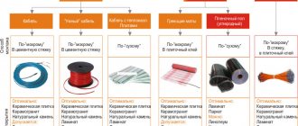
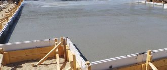
A pile foundation is an opportunity to build buildings on soils that do not allow the use of any other type of supporting structure.
A feature of piles is their ability to sink to the required depth, reach dense layers of soil and provide a reliable foundation for buildings of any category, including the most massive, critical and specific ones.
The possibilities of a pile foundation are very wide, which is clearly demonstrated by the number of varieties and design options for supports.
There are powerful and heavy samples that can only be worked with using construction equipment.
There are also lighter types available for self-installation, for example, screw piles.
Types of pile foundations
The classification of pile foundations includes many positions.
They differ in the following characteristics:
- Method of action (hanging and pile-racks).
- Barrel type (monolithic and shell)
- Material (wooden, metal, reinforced concrete)
- Immersion method (driving, bored or screw).
NOTE!
In private housing construction, the most common are bored and pile-screw options, which allow working in densely built-up areas without causing damage to surrounding buildings.
Methods of classification and types of pile foundations
The total number of types and subtypes of pile foundations is about 30 design options. Let's consider the main types of pile foundations that are used for the construction of private houses and cottages. They are divided into types according to the following criteria:
- Material of manufacture. Piles are made of metal, concrete, reinforced concrete. There are also wooden ones, which are most often used for the construction of temporary buildings.
- Section shape: round, rectangular and square. Piles can be pointed or thickened at the lower end, and have an even cross-section.
- The size (length) depends on the calculated data, the depth of hard rock, the depth of soil freezing and other factors. The average length is from 2 to 6 meters.
Another way of dividing into subspecies is based on the principle of their work in the ground. There are two types: pile-racks and hanging structures.
Rack piles most often have a sharp end, with which they cut through soft soils when buried. This type has a smooth surface that does not create additional friction. They are buried down to hard rocks, to which they transfer the load-bearing load from the structure located on them.
Hanging piles have uneven, rough and protruding side faces. This design allows you to create good traction with the ground, because the piles are held in it due to the friction force against the side walls. This type is used in cases where strong and hard rocks lie too deep, and also if the lower layers are not able to withstand the load from the racks.
Types of piles
Screw piles have two main types:
- Welded.
- Cast.
The difference between them is the design of the tip. This is an important element that takes on the main load during a dive.
The quality of the tip determines how the pile will behave when it comes into contact with a man-made or natural obstacle that is not a dense soil layer. Welded tips are less durable in this regard; when encountering rock fragments, they are often deformed and fail.
The cast tip is much stronger and is able to pass obstacles, destroying them and without losing the functionality of the pile.
In addition, there are differences in the number of blades.
There are screw piles:
- Single bladed.
- Multi-lobed.
Single-blade piles have a single spiral-shaped blade that provides translational motion as the pile rotates around a vertical axis. They are designed for installation in relatively soft and homogeneous soil that does not have dense or rocky inclusions.
The bearing capacity of such piles is lower than that of multi-bladed samples, which are much more stable and more firmly connected to the ground. The presence of several support units makes it possible to reduce the diameter of the barrel, which facilitates installation and ensures structural integrity.
Complete with a cast tip, they are optimally suited for working on dense soils, in permafrost zones or with a large number of man-made inclusions.
Based on the type of protective coating, piles are divided into galvanized and non-galvanized . The latter are practically not protected in any way from the effects of ground moisture, since the layer of paint, which is applied to give the products greater solidity, comes off when screwed.
In addition, all types of screw piles are practically not protected from electrochemical corrosion or the effects of stray currents, which is difficult to foresee or determine in advance.
Scope of application of pile foundations and their components
Home Favorites Random article Educational New additions Feedback FAQPile foundations are widely used both in bridge construction and in other areas of construction. The effectiveness of these foundations is due to a more complete use of the bearing capacity of the soil foundation and the strength of the foundation elements. The development of the construction industry contributes to the improvement of technology for constructing pile foundations and a significant reduction in economic costs.
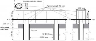
In Fig. 4.1 shows a general diagram of a pile foundation.
|
According to this scheme, a pile foundation consists of two main elements: piles (shell piles or pillar piles) and a slab that unites them at the top and is called a grillage slab. The height position of the pile foundation elements is indicated by the following marks: - edge of the grillage slab, - bottom of the grillage slab, - top (head) of the piles, - lower end of the piles. The pile can be completely located in the ground. The depth of immersion of the pile into the ground, counting from the bottom of the grillage slab, is indicated. The grillage slab can rise above the ground. In this case, the section of the pile above the ground is called the free length and is designated.
The scope of application of pile foundations can be determined by soil conditions, technological capabilities, as well as economic feasibility. The use of a pile foundation is certainly justified if the foundation is composed of weak soils in the upper part and stronger rocks in the lower part. Then the piles penetrate weak layers of soil and transfer the load from the structure to the underlying low-compressible horizons.
In areas covered with water and with a significant depth of the watercourse, the construction of a pile foundation may be the only possible one for technological reasons. The construction of a massive shallow foundation in such conditions is fraught with great difficulties, while the driving of piles from watercraft and the subsequent installation of a grillage slab has been technologically proven.
Finally, there are often cases when it is possible to construct both a shallow foundation and a pile foundation. Then designs for both foundation options are developed and the choice of foundation type is made based on economic indicators.
Improving the designs and technology of constructing pile foundations is one of the main tasks in the field of transport construction.
Types of piles
The piles used in construction differ in several ways: in the material from which they are made, in their size and shape, in the method of installation in the ground, and others [1]. It should be borne in mind that the classifications of piles are undergoing changes as their designs and manufacturing technology are improved, and new types of piles appear. Let us consider the existing pile designs currently used in construction using several classification criteria.
First, let's look at a few definitions. A pile is an element - wooden, concrete, reinforced concrete or steel, hollow or solid, immersed in the ground (in the case of a hollow element with a closed lower end) with a cross-sectional diameter of no more than 0.8 m.
A shell pile is a hollow reinforced concrete or steel element immersed in the ground with an open lower end and excavation of soil from an internal cavity with a diameter of 1 ... 3 m.
A pillar pile is an element, usually made of reinforced concrete at the construction site in a pre-drilled hole with a diameter of more than 0.8 m.
These definitions are somewhat arbitrary and do not cover the entire variety of pile structures. Here they are given for an initial acquaintance with piles. So, let's look at the most common types of piles.
First of all, let's get acquainted with piles that are immersed in the ground in finished form.
Wooden piles.
Wooden piles are usually used where wood is the local building material. They are prepared from coniferous forests, mainly from pine and larch with healthy wood, with a diameter of 18 to 40 cm and a length of 4.5–8.5 m. Longer logs are scarce and are made to special order. Winter-cut forest with unlimited humidity is recommended.
Logs for piles are cleaned of branches, growths and bark. The natural conicity of the logs is usually preserved. Sometimes logs for piles are cylindered.
The piles are immersed in the ground with a thin end, which is sharpened on 3 or 4 edges (Fig. 4.2, a, b
).
A more gentle point is made for driving piles into denser soils. If the soil contains solid inclusions (gravel, pebbles, etc.), the tip of the pile is protected with a steel shoe (Fig. 4.2, b
), which is secured with nails. The sharpening is carried out strictly along the axis, otherwise the pile will move to the side when immersed.
The upper end (head) of the pile is cut strictly perpendicular to the longitudinal axis and strengthened from loosening when driven in with a steel ring-yoke made of a strip 12–20 mm thick and 50–100 mm wide (Fig. 4.2, c
).
The logs in the pile can be increased. The joint along the length of the pile is made no more than once, strictly at the end and fixed with a steel pin along the axis of the logs and strip or corner plates with a length of 2.5–3 times the diameter of the pile (Fig. 4.2, d
).
Instead of linings, steel pipes are also used (Fig. 4.2, d
). After driving the piles, the joints should be 2 m below the level of possible erosion, and for adjacent piles they should be at different levels with a height difference of at least 0.75 m.
Longer wooden piles (up to 25 m) are made in batches of three or four logs (Fig. 4.2, f
) or glued waterproof compounds from boards or beams (Fig. 4.2,
g
).
| Rice. 4.2 Wooden piles (dimensions in cm) |
The joining of logs in stacked piles is carried out with a spacing of at least 1.5 m. The lower end of the stack of logs is protected with a common steel shoe, and the upper ends of the logs with a common yoke.
Wooden piles are cheap, easy to manufacture, and light in weight, which makes them easy to transport and bury in the ground. However, they have a limited length and therefore a relatively low load-bearing capacity [2]. The production of package piles from logs requires a lot of metal, which greatly increases their cost. In addition, wooden piles are susceptible to rotting in conditions of variable humidity. Therefore, in permanent structures, the heads of wooden piles are located below the lowest water level by at least 0.5 m. In sea water, where there are wood pests (horned cherries, etc.), wooden piles are not used.
Driven reinforced concrete piles of continuous section
In bridge construction, standard prismatic reinforced concrete piles of square section 30´30, 35´35 and 40´40 cm with conventional or prestressed reinforcement are widely used. Rectangular piles of 25´30, 30´35 and 35´40 are less commonly used [2, 3].
In foundation building practice, three-, six- and octagonal prismatic piles of solid cross-section are also used.
Bridge piles are non-crack-resistant (with permissible crack opening of no more than 0.2 mm), which are made from ordinary reinforced concrete with a low percentage of reinforcement so that they are strong in bending from their own weight during installation. The longitudinal (working) reinforcement of such piles consists of four periodic profile rods placed in the corners of the pile section. The length of such piles is from 4 to 12 m. They are intended for foundations with a low grillage with small horizontal loads.
Crack-resistant bridge piles (with a permissible crack opening of no more than 0.1 mm) made of ordinary reinforced concrete of class B20 to B35 have a higher percentage of reinforcement and a length of 4 to 18 m. At the same time, for larger piles a higher class of concrete and a higher percentage of reinforcement. The working reinforcement, located in the cross-sectional corners of such piles, consists of 1–3 rods of a periodic profile of class A-II with a diameter of 20 to 28 mm (Fig. 4.3).
At the tip of the pile, the working reinforcement is bundled around a fixing pin, and the head of the pile is reinforced with welded mesh. The pitch of the transverse spiral reinforcement at the ends of the pile, where the greatest stresses arise during driving, is taken to be less than along the length of its middle part. For slinging piles, slinging loops are provided, located in places along the length of the pile based on the equality of bending moments from its own weight at the slinging points and in the span.
| Rice. 4.3 Bridge prismatic reinforced concrete pile: a - formwork drawing; b - types of pile reinforcement; c - reinforcement of the pile tip |
Typical prestressed piles of solid square cross-section for the foundations of transport structures have a length of 8 to 20 m. They are made of class B35 concrete and reinforced either with bar reinforcement of a periodic profile of class A-IV with a diameter of 12–20 mm, or with high-strength wire of a periodic profile of class BP-IV II with a diameter of 5 mm. For high grillages of bridge foundations, prestressed piles with rod reinforcement are used.
Bridge piles for normal climatic conditions have a protective layer of concrete 30 mm thick, and in the northern version - 50 mm.
In the current catalogs of piles, each standard size is assigned its own brand. For example, the SM12-35T4 brand corresponds to a pavement pile (SM) 12 m long with a section of 35´35 cm, crack-resistant (T) with type 4 reinforcement; grade SN-12-35 corresponds to a prestressed pile (SN) 12 m long with a cross-section of 35´35 cm.
The main disadvantage of solid driven piles is their large mass, which makes them difficult to transport and requires the use of heavy crane and piling equipment. To a lesser extent, these disadvantages are inherent in hollow piles, which are most often made in a cylindrical shape.
Precast concrete shell piles
Hollow reinforced concrete piles of annular cross-section are assembled from separate sections with an outer diameter of 0.4; 0.6; 1.2; 1.6; 3.0 m, length from 4 to 12 m with a diameter from 0.4 to 1.6 m and length of 6 m with a diameter of 3.0 m [1, 3]. The wall thickness of shells with a diameter of 0.4–0.6 m is 8–10 cm, and with a diameter of 1.2–3.0 - 12 cm. Shells with a wall thickness of 15–20 cm (thick-walled shells) were also used in bridge construction.
Small diameter shell piles can be installed to their full length before being driven. With a large diameter, the sections of the shells are increased as they are immersed, so that the total length of the piles can reach 50 m or more. After immersion in the ground, the cavities of the shells are filled with concrete (sometimes reinforced), sand, or left hollow.
Shell sections are made of ordinary or prestressed concrete of class B35 concrete. To fill the cavity of the shells, concrete of classes B20 and B25 is used. Longitudinal reinforcement is placed in thin-walled shells in the middle of the wall thickness in one row evenly across the cross-section. In thick-walled shells, a two-row arrangement of longitudinal reinforcement along the wall thickness is adopted. In shells made of ordinary reinforced concrete, periodic profile reinforcement of class A-II with a rod diameter of 16–25 mm is used, and in prestressed shells, class A-IV is used. Transverse spiral reinforcement is made of wire with a diameter of at least 6 mm in increments of 10 cm, and at the end sections of each section - 5 cm. Typical shells made of ordinary reinforced concrete with the same diameter can have a different percentage of reinforcement: m = 2; 2.5 and 3% - with a shell diameter of 0.4 and 0.6 m and m = 1.5; 2.0; 3.0 and 5.0% - for large diameters. Figure 4.4 shows one type of reinforcement for a shell with a diameter of 0.6 m. Typical shells made of prestressed reinforced concrete have the same percentage of reinforcement (m = 3%).
| Rice. 4.4 Section of reinforced concrete shell: 1 - shell; 2 - longitudinal reinforcement; 3 - spiral reinforcement; 4 - short pieces from reinforcement |
Sections of shells with a diameter of 0.4–1.6 m are produced in centrifuges, and sections with a diameter of 3.0 m are made in vertical vibration molds. In piles they are connected to each other by a flange-bolt joint (Fig. 4.5, a
) or welded (Fig. 4.5, b). Shells made of prestressed concrete and shells with a diameter of 3.0 m are connected only at flange-bolt joints.
To protect against corrosion, the joints are cemented with concrete on quick-hardening cement, and the joints located in the ground are filled with hot bitumen.
Shells with a diameter of 0.4 and 0.6 m are usually immersed with a closed lower end, for which special tips are used, attached to the end of the lower section of the pile (Fig. 4.6, a
). In this case, the interaction of the shell with the soil during the driving process is no different from solid piles.
Shells of larger diameter are immersed with an open lower end, for which purpose an annular steel knife is installed in their lower part (Fig. 4.6, b). To reduce the resistance of such a shell to immersion, simultaneously with immersion, soil is excavated near the knife through the cavity of the shell. At the same time, the soil around it does not experience significant additional compaction, which occurs when driving piles with a closed lower end, which affects their load-bearing capacity. In this regard, the load-bearing elements of pile foundations made of shells with a diameter of up to 0.6 m are called piles, and those with a larger diameter are called shell piles.
| Rice. 4.5 Joints of sections of reinforced concrete shells: a - flange-bolt; b - welded |
| Rice. 4.6 The lower end of reinforced concrete shells: a - blind tip, b - ring knife |
Steel and steel concrete piles
Steel piles are made from rolled profiles (I-beams, channels, angles) or from welded or seamless pipes [2]. To increase the rigidity of steel piles, rolled profiles are connected by welding or rivets into packages of box-shaped, T-section or cross-section. Such piles can be immersed in soils containing solid inclusions and used to pierce thin layers of semi-rocky soils or destroyed rock layers.
In terms of metal costs and manufacturing complexity, piles made of steel pipes are more preferable. Their links are joined on racks to their full length, and when the length of the piles is more than 25 m, they are extended by links during the immersion process. The joints are made welded with overlays (Fig. 4.7, a
), and the lower ends are blind (with a closed tip made of the same pipes, Fig. 4.7,
b
) or open. Steel shells with a diameter of more than 1 m are immersed only with an open lower end and the soil is removed from them. The shell cavity is filled with concrete of class B20 or B25 (steel concrete piles). The length of such piles can reach 50 m.
| Rice. 4.7 Structural elements of the shell of a steel concrete pile: a - welded joint of sections; b - blind steel tip |
The disadvantage of steel piles is the high consumption of metal and susceptibility to corrosion. The corrosion rate of steel under water is 0.014–0.05 mm/year, and in a zone of variable humidity it can reach 0.4–0.5 mm/year. To protect piles from corrosion, their surface is coated with asphalt paints or coal tar.
Screw piles.
A screw pile (Fig. 4.8) consists of a steel or reinforced concrete shaft and a steel or cast iron shoe equipped with helical blades.
The screw pile shoe is made cast or welded. The helical blade has a length of 1.25–1.5 turns and a diameter equal to 3–4.5 times the diameter of the pile shaft. Blade pitch at trunk diameter d
£ 60 cm is assigned equal to (0.6–0.8)
d
, and with a larger diameter - (0.35–0.4)
d
.
| Rice. 4.8 Screw pile: 1 - steel shell; 2 - shoe with helical blade |
Screw piles are driven by screwing them with special capstan mechanisms. Immersion is possible in vertical and inclined positions into non-cohesive and cohesive soils, including the inclusion of boulders smaller than the pitch of the helical blade. In construction practice, screw piles with a blade diameter of 3.0 m and a length of up to 50 m were used. The screw blade increases the supporting area of the lower end of the pile, which significantly increases its load-bearing capacity. In addition, screw piles, due to the same blade, are able to withstand significant pull-out loads, and therefore they can be used as anchors.
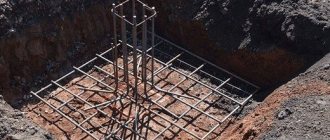
Driven and drilled piles
This type of piles is manufactured directly at the construction site [1, 2, 3]. To construct a pile, a well is first installed in the ground by drilling or punching.
Punching a well is carried out without removing soil from its cavity and, therefore, soil compaction takes place in the near-well zone. The well is filled with concrete mixture in portions, compacted and pressed into the ground. As a result, a corrugated surface is formed, providing increased adhesion of the pile to the soil (Fig. 4.9, a). Such piles are called cast-in-place piles. This type includes Frankie piles, frequently rammed piles, Simplex, Stern piles, etc. (Fig. 4.9, b).
Rice. 4.9 Rammed pile: a-frequently rammed, b-Franki pile
Drilling wells in stable soils can be carried out without securing the walls of the wells. If there is water or the possibility of collapse of the walls of the wells, they are secured using clay mortar or casing pipes. After the well is constructed, a reinforcement cage is installed and the pile body is concreted. Casing pipes are usually removed from the ground. The concrete mixture can be placed with compaction. Such piles are called bored piles (Fig. 4.10). The diameter of bored piles can be 0.8 ... 2.5 m. The length of bored piles reaches tens of meters. If necessary, a widening is made at the level of the lower end of bored piles. The widening diameter is 2.5 ... 3.5 m. Bored piles with a widened heel have increased load-bearing capacity. It is advisable to use widening when the drill pile rests on strong rocks.
Drilling systems are pre-installed piles in pre-drilled wells. The gap between the pile and the walls of the well is filled with cement mortar (Fig. 4.11).
Camouflage piles
To increase the bearing capacity of hollow driven piles and drilled pillar piles, their lower end is widened by camouflage using an explosive charge [2]. The technological diagram of the installation of camouflage piles is shown in Fig. 4.12.
After immersing a reinforced concrete or steel shell with a closed or open (with soil excavation) lower end into the ground, a charge with an electric detonator connected by wires to a blasting machine on the surface is placed at the lower end of the shell.
| Rice. 4.12 Camouflage pile: 1 - shell; 2 - explosive charge; 3 - electrical wires; 4 - cast concrete mixture; 5 — camouflage widening; 6 - reinforcement cage |
The shell cavity is filled to a certain height with cast concrete and the charge is detonated. The lower end of the shell is destroyed by the force of the explosion, and the soil in this place is compacted to form a nearly spherical cavity (camouflage), which is filled with cast concrete from the shell cavity. The shell is then filled with concrete mixture to its full height.
The mass of the charge is assigned depending on the required diameter of the camouflage widening and is specified on site by experimental explosions. The diameter of the widening is controlled by measuring the levels of concrete in the well before the explosion ( ) and after it ( ). It is necessary that after the explosion, a column of concrete with a height of at least 2 m remains in the cavity of the shell. To protect the barrel of the reinforced concrete shell from destruction during an explosion, a steel cartridge is attached to its lower end, at the bottom of which a charge is placed. The explosion destroys the lower part of the cartridge, but the walls of the shell remain intact.
Camouflage widening can also be performed for bored piles by exploding a charge at the bottom of the well and pouring cast concrete mixture into its cavity to the calculated height. After the formation of a camouflage widening, sometimes a reinforced concrete pile is lowered into the well (drilled piles with a camouflage heel).
Types of pile foundations.
The types of pile foundations are determined depending on a number of factors. Such factors include: the shape and dimensions of the pile field, the location of the grillage slab relative to the ground surface, the nature of the interaction of the constituent elements of the pile foundation with the base [1].
Linear above-ground structures, such as walls, have one or more rows of piles united on top by a slab of sufficient length, representing a strip pile foundation. Free-standing pile foundations are based on a cluster of piles and are usually installed under bridge supports or columns of buildings and structures. Finally, a large foundation slab can rest on a single pile field.
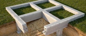
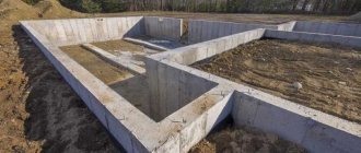
Pile foundations with a low grillage. This type includes pile foundations with a grillage slab buried in the ground - the mark of the bottom of the grillage slab is located below the level of the layout or the mark of local erosion (Fig. 4.13). Such foundations are built on dry lands, as well as in river beds with heavy ice conditions or in the presence of zones of intense abrasive action of alluvium, moved by the fast flow of the river. The operation of pile foundations with a low grillage proceeds in a favorable mode in that not only the piles, but also the soil, acting on the side surface of the grillage slab, resist horizontal loads. The construction of a grillage slab in the ground is associated with additional costs for the construction of a pit and its fencing [2].
| Rice. 4.13 Pile foundation with low grillage |
In pile foundations with a high grillage, the slab is located above the ground surface - the mark of the bottom of the grillage slab is above the level of the layout or the mark of local erosion (Fig. 4.14).
| Rice. 4.14 Pile foundation with a high grillage |
This type of foundation has become widespread in bridge construction as an economical and reliable design. They are less material-intensive compared to massive foundations or pile foundations with a low grillage, do not require excavation and, therefore, allow the use of lighter fences in the riverbed. To carry horizontal loads in pile foundations with a high grillage, inclined piles are used. Shell piles and large-diameter drill columns are widely used here [1, 4].
In some cases, in pile foundations, the grillage slab is missing as an independent element. Its functions are performed by a support in its lower part, directly resting on the piles. Such structures are called pile supports (Fig. 4.15). It is advisable to use this method of constructing the foundation part when the required dimensions of the grillage slab in plan do not exceed the cross-section of the support in the lower part [4].
| Rice. 4.15 Pile support |
Grillless supports (overpass type) have become widespread in the construction of overpasses and floodplain sections of bridge crossings [1, 4]. In these supports, the undertruss slab acts as a grillage slab, connecting the heads of the piles and transferring the load from the spans to them (Fig. 4.16). If the overpass part of the bridge crossing is long, it is advisable to use precast reinforced concrete and use continuous construction technology for installing grillage-free supports. Under these conditions, grillage-free supports are highly economically efficient.
| 4.16. Grillless supports of a pile-overpass bridge |
In the types of pile foundations considered, the main load-bearing element is piles. It is through them that the load is transferred to the base. The grillage plate ensures that the piles work together. At the same time, if the slab is buried in the ground and rests on sufficiently strong rocks, then resistance forces to vertical movements will develop along the base of the grillage slab, having a significant impact on the operation of the foundation as a whole. If the slab transfers at least 15% of the total load to the ground through its base, then such structures are called combined pile-slab foundations (Fig. 4.17) [5, 6].
| Rice. 4.17 Pile-slab foundation |
When the piles account for less than 50% of the total load, the foundation is called a combined slab-pile foundation. Ensuring the joint work of piles and a grillage slab buried in the ground allows for more complete use of the load-bearing capacity reserves of the pile foundation. Combined pile-slab and slab-pile structures are used as the foundation part for structures of large size and weight, such as high-rise buildings. In transport construction, this type of foundation can be useful in the construction of pylons for suspension and cable-stayed bridges of large spans.
4.4 Load-bearing capacity of piles
4.4.1 Concept of load-bearing capacity of piles
When an axial pressing load is applied to the pile in the soil, resistance forces to the movement of the pile develop. Distributed friction forces act along the side surface (calculated soil resistance along the side surface of the pile), and normal pressure acts along the end of the pile (calculated soil resistance under the lower end of the pile). The total value of the maximum resistance forces is called the bearing capacity of the pile for indentation along the ground.
If the pile rests on compressible soils and has the ability to move in the axial direction, then the resistance forces develop equally - both along the side surface and along the end (Fig. 4.18, a, b). Such piles are called hanging piles.
| The load-bearing capacity is determined by the sum, where the term is due to friction forces, and the component is due to drag. For piles with a widened lower end, the resistance along the lateral surface is not taken into account in the lower section of the pile shaft (Fig. 4.18, b). The dimensions of this section are determined by a cone with a generatrix inclined to the axial direction at an angle and touching the edge of the widening (is the weighted average value of the angle of internal friction of soils within the height of the cone). If the pile rests on practically incompressible soils, then the load-bearing capacity of the pile is determined mainly by the design resistance: (Fig. 4.18, c). Friction forces can come into play at the final stage, when the soil under the lower end has exhausted its strength. However, this stage of pile operation is unacceptable. In this case, practically incompressible rocks include rocky soils, coarse soils and clays of a solid consistency. Piles resting on these soils are called rack piles. The load-bearing capacity of a pile for indentation along the ground is determined by both calculation and field methods. The ability of a pile to withstand pull-out loads is characterized by the load-bearing capacity of the pile for pull-out along the ground. For piles without widening, this value is determined only by friction forces on the lateral surface: (Fig. 4.19, a). The presence of a widening at the lower end of the pile creates additional resistance to pulling out the pile due to forces normal to the upper plane of the widening (Fig. 4.19, b).
In addition to axial force, the pile can absorb transverse and moment loads. The maximum values of these loads are established as a result of calculating the pile as a rod located in an elastic medium. The criterion for the admissibility of transverse and moment loads is the limitation of the amount of movement of the pile head, as well as the strength condition of the soil surrounding the pile. It should be noted that in some cases the load-bearing capacity of a pile under the action of a horizontal force is established experimentally or using special theoretical solutions. To ensure the operation of the pile in the ground, the strength of the pile as a structural element is also assessed. The bearing capacity of the pile in terms of material in tension and compression is determined in accordance with the rules for calculating building structures. In addition, the strength of the most loaded section of the pile under the combined action of normal force and bending moment is assessed. 4.4.2 Calculation method for determining the bearing capacity of piles on the ground To determine the load-bearing capacity of a suspended pile for indentation along the ground, a design scheme is drawn up, dividing the base within the depth of the pile’s immersion into the ground into design layers (Fig. 4.20). Bearing capacity is determined as the sum of its components and according to the formula [6, 7]: (4.1) where g c — coefficient of working conditions of a pile in the ground, taken equal to 0.8 for cast-in-place, drilled piles, shell piles driven with soil excavation, when resting them on clayey soils with a moisture content
The first term in formula (4.1) expresses the component of the load-bearing capacity of the pile due to the soil resistance along its base, the second - the component due to the total frictional resistance of the soil along the side surface of the shaft. The summation is performed over all layers of soil that the pile cuts through. Values of calculated soil resistance R for driven piles and shell piles immersed in the ground with a closed lower end, when resting them on sandy and clayey soils, take Table 4.1 [6, 7]. Calculated soil resistance under the lower end of the driven pile Table 4.1
Notes: 1. The numerator shows R for sandy soils, in the denominator - for clay soils. For bored piles with or without widening and shells driven with an open lower end and with soil excavated from their cavity when resting on clay soils, R taken according to table 4.2 [6, 7]. Calculated soil resistance under the lower end of a bored pile Table 4.2 Note . Previous10Next |
Which ones are best suited for private construction?
The choice of a specific brand and size of trunks is, first of all, made based on the type and characteristics of the soil.
After determining the most suitable variety (single or multi-bladed, length, tip type), the trunk diameter is selected. The calculation is made based on the bearing capacity of the support.
For private houses, trunks of relatively small diameter are usually used:
- VS-57.
- VS-76.
- VS-89.
- VS-108.
Large diameters require significant effort when immersing, so they are practically not used for private housing construction.
Pile foundation - advantages and disadvantages
The advantages of such grounds include the following aspects:
- The ability to erect a building in difficult areas when other types of foundations cannot be used.
- Relatively low labor intensity and high installation speed.
- Minimizing construction costs, since a pile foundation is considered one of the cheapest options.
- The absence of excavation work allows you to preserve the natural landscape at the construction site.
Among the disadvantages of this type of foundation, the following factors are noted:
- The need for calculations, since piles have a limit on their bearing capacity.
- No basement.
- This type of foundation is suitable for the construction of relatively light structures.
- The need to tie the piles, as well as their high-quality waterproofing.
- The complexity of arranging the floors of the first floor: the use of effective thermal insulation materials is required to prevent freezing.
Important! Engineering geological surveys and calculations of pile foundations should be carried out by specialists in this field. Even minor miscalculations lead to subsidence of piles, which causes deformation and even destruction of erected buildings.
What soils are they suitable for?
The screw piles are driven to a sufficient depth to eliminate the impact of vertical loads of frost heaving. Only lateral influences remain, which, due to the small contact area, are not capable of exerting a decisive influence on the supports.
Therefore, when determining the suitability of a soil, it is customary to consider only mechanical qualities.
The most suitable types are the following types of soil (in descending order of suitability)::
- Sandy.
- Sandy loam.
- Loams.
- Clayey.
Absolutely unsuitable soils are rocky and rocky-clastic types. In addition, biogenic types - peat bogs, or loose subsidence soils - are contraindicated.
Caution should be exercised in heavily flooded areas subject to strong seasonal fluctuations in groundwater levels..
When constructing in such areas, it is necessary to carry out test drilling and increase the immersion depth to the maximum.
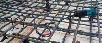
General scheme for installing a pile-screw foundation
Step-by-step instructions for installing piles with your own hands consists of the following steps:
- Preparatory work. Marking the site, checking the parallelism of the lines and compliance with right angles.
- Immersion of corner shafts.
- Installation of intermediate supports.
- Trimming trunks. The surface of the supports should form a flat horizontal plane.
- Concreting the internal cavities of piles to enhance strength.
- Installation of heads. They are installed on the upper end, welded and serve as attachment points for the grillage. All areas located near the weld or areas with damaged protective coating are immediately touched up.
IMPORTANT!
When marking, you should proceed from the axes of the walls, and not from the boundaries of the perimeter of the house. Walls should stand on the heads and not hang from them.
How to calculate the amount of material?
The number of supports is calculated in two directions:
- Along the lines of the greatest load.
- According to the bearing capacity of the pile.
The first stage consists of counting the number of piles along all lines of the external and internal load-bearing walls. The distance between them should not exceed 2-3 m (the heavier the house, the closer to each other the supports should be installed).
The second stage is to check the resulting number of supports. The total weight of the house, together with the calculated additional loads (the weight of snow, furniture and household appliances, floors, people, etc.) must be divided by the permissible load on one pile.
If the resulting number is less than what was found in the first stage, then the calculation is correct. If the second stage shows a higher value, it is necessary to increase the number of piles along the load lines.
You can do it easier and use an online calculator, which will do the entire calculation on its own. You just need to insert your parameters into the required fields and get an answer.
How to correctly mark installation locations?
To perform this operation, you will need a plan of the first floor of the house. First, corner points and junctions of load-bearing walls, internal and external, are marked. Then the remaining number of piles is evenly distributed along all lines.
If there are large gaps, provide intermediate supports to support the floor beams.
NOTE!
A distance of more than 6 meters between supports is considered unacceptable.
How to determine diving depth?
Determining the immersion depth of the supports can only be done on the basis of an analysis of the soil and its composition. In addition, an important factor is the depth of soil freezing, above which it is not recommended to bury piles, especially for critical (residential) buildings.
For auxiliary buildings and structures (gazebos, fences, sheds, etc.) erected on suitable soils, the minimum immersion depth is 1.5 m.
For residential buildings, the recommended immersion depth should be equal to the height of the house . In practice, it is often less, which is primarily due to illiteracy or the desire to reduce builders’ time.
When diving, you must know the maximum value of soil resistance and not exceed the permissible limits established by the manufacturer. Otherwise, there is a risk of collapsing the technological hole before reaching the required depth, which means the pile will be damaged and will need to be replaced.
Immersion of piles into the soil
There are two ways to drive piles:
- Manual diving.
- Mechanical method.
Manual installation is allowed only for relatively thin piles and during the construction of non-critical auxiliary structures. For residential buildings it is necessary to use construction equipment . First of all, this is due to the inability to properly screw in a pile with a diameter of 108 mm by hand.
The failure rate of piles is too high, and reverse is unacceptable due to the loss of proper connection strength. In addition, the permissible vertical skew of the barrel is only 2°, which is impossible to ensure manually.
The mechanical method allows you to ensure high-quality immersion while maintaining the vertical and a given amount of force . For residential buildings, only the mechanical method is permissible, although advertisements in every possible way claim that it is possible to act in any situation with the help of muscular force.
This creates the opportunity for various violations when inexperienced builders begin to act on their own and, as a result, end up with an unstable and moving foundation. In practice, a mini-excavator with a mounted pile driver is usually used.
It is capable of immersing trunks with a diameter of up to 159 mm to a depth of up to 12 m, which in most cases is quite sufficient for private construction.
How to align horizontally
Submerged screw piles must be leveled horizontally. To do this, install a laser building level (you need a model that can outline a horizontal plane) at the required height from the soil surface.
All trunks are trimmed according to the existing mark . If any of them are too short, a preliminary extension is made.
An additional pipe is welded to the trimmed part of the trunk (the section with the technological hole is cut off), increasing the missing length, after which trimming is performed at the general level.
All welds and areas of metal exposed during trimming must be immediately tinted with protective polymer paint. It is necessary to choose types that are impervious to moisture or use bitumen mastic.
Pouring concrete
The internal cavities of the piles are filled with concrete. This allows you to significantly increase the mechanical rigidity of the pipe and reduce the risk of corrosion inside the barrel.
Concreting increases the load-bearing capacity of the trunk by a third, allowing you to obtain a certain margin of strength for the foundation, necessary for resistance to unforeseen situations . For pouring, dense grades of concrete are used - M200 and higher. Filling is done to a level slightly lower than the cutting height.
In the first hours, the concrete in the well will sag by several centimeters, so after filling, a dry sand-cement mixture is poured to the top of the shaft. It will absorb water particles squeezed out during subsidence and form a plug that seals the barrel before installing the head.
Principles of calculation and design
The pile-screw technology for constructing foundations is based on the principle of passing a point support through weak layers of soil to dense bearing layers.
The load from the house is thus transferred directly to the load-bearing soil foundation, which ensures a reliable and durable position of the structure.
The depth of the load-bearing soil layers is determined by experimental drilling and taking soil samples, followed by their testing. This parameter is also taken from a vertical survey linked to the construction site, which is available in every architecture department of the local executive committee.
By collecting loads (the weight of all building structures, furniture, equipment for various purposes, the maximum number of people, etc., snow load) and dividing them by the total area of the screw piles, the specific pressure on the soil is determined . It should be less than the resistance of the load-bearing soil layer. This ratio is used to adjust the number of screw piles on the SVF plan.
Based on the number of piles, the type of supporting soil layer and the factory data on the load-bearing capacity of standard screw piles, the type and brand of aircraft is determined.
The versatility and quick installation of SVF attracts many developers to build foundations not only in places where heaving soils are located, but also on quite strong load-bearing foundations. The only exception is rocky soils, which, with their solid inclusions, can damage and completely destroy the blades of screw piles.
There are standards for selecting standard sizes of piles for the construction of various objects . The main indicator is the diameter of the support trunk, which is directly related to the magnitude of its load-bearing capacity. For manual installation of piles, supports with a diameter of 57 to 133 mm are used.
| Pile diameter, mm | Load, kg | Soil type | Structure |
| 57 | 800 | Waterlogged soil | Lightweight frame buildings |
| 89 | 1400 | Swampy and peat bogs | Country houses, garages |
| 108 | 3500 | Everything except the rocky ones | Log houses (log houses) |
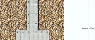
The length of the pile is calculated based on the fact that its lower end must be immersed in the load-bearing soil layer by at least 300 mm. To this add the height of the ground part of the support. The construction project specifies the amount of clearance between the ground and the aircraft frame (grillage).
The minimum technological gap allowed is 150 mm high . Here you should add the distance to the technological holes + 100 mm. In total, this will be the optimal length of the pile.
Practical experience shows the advisability of manual installation of screw supports with a length of up to 1.8 m. For larger sizes, installation of SVF is possible only with the help of special equipment.
How to draw up a drawing of a pile field?
After all the calculations, they begin to create a drawing of the aircraft location on the construction site plan.
When placing supports on a personal plot, the following rules are followed:
- Piles should be installed at all corners of the foundation plan.
- Supports for a monolithic slab for equipment (furnace, boiler, etc.) will be in the corners and along the perimeter every 1.5 m.
- Along the axes of the load-bearing walls, the centers of the piles are placed at intervals of 1.5 to 2 m, depending on the material of the grillage (framing). For example, for a beam - 1.5 m, and for a channel it will be enough to install supports every 2 - 2.5 m.
An example of an as-built diagram and plan of a pile-screw foundation:
Grillage strapping
A grillage is a strapping belt that connects individual supports into a single system. It is needed to bear the weight of walls or other structural elements of the house and distribute the load evenly across the entire pile field.
There are different methods for installing a grillage, depending on the material of manufacture.:
Wood
A wooden beam with a minimum thickness of 150:150 mm is used. As an option, you can use packs of boards 50 mm thick and 200 mm wide, connected into a single package measuring 150: 200 mm. High-quality dry lumber of grade 1 or 2 is used.
The surface of the wood is coated with an antiseptic and fire-retardant composition (currently there is an impregnation that performs both functions). The connection of the beams is made halfway across the tree and only above the head of the pile.
Joints located in the span are not allowed. A double layer of roofing material (waterproofing) is laid between the metal and wood in all places. The installation is carried out so that the pile is located exactly along the longitudinal axis of the beam.
Metal
Various types of rolled metal are used:
- Channel.
- I-beam
- Rectangular pipe.
When using a channel, no heads are needed, although their presence is required for a pipe or I-beam. For the channel, special embedded parts are used, installed in the pipe when pouring concrete.
It becomes possible to do without waterproofing between the heads and the trim, but between the metal and the wall it is used in any case . The parts are connected by welding with mandatory reinforcement with bolts.
With increased strength of the metal grillage, a large metal structural element appears that requires maintenance - periodic painting with protective compounds.
Reinforced concrete
This is the most labor-intensive and time-consuming option for creating a grillage, but also the most durable and reliable, not subject to corrosion or rotting. To create it, it is necessary to make formwork installed on top of the heads.
A reinforcement cage is placed inside, after which they begin pouring concrete.
The inside of the formwork is covered with a layer of roofing felt or polyethylene to prevent moisture leaks. Sometimes the grillage is poured below the level of the caps, welding the reinforcement cage directly to the trunks. Most often this is done at a sufficient height at ground level.
In such cases, horizontal trimming is carried out after the concrete has hardened (28 days), and the filling of the trunks is carried out after trimming.
Pouring the ground part of the pile foundation
If the ground allows, and the building site is relatively flat, the grillage is often made directly on the ground. To perform such an operation, the head should not rise above the ground level by more than 100 mm. After all the supports are installed, they begin preparing and pouring the strip foundation on the piles. This is done using the following technology:
- The top of the soil is removed along the perimeter of the foundation to create a small trench.
- The next step is the construction of removable or permanent formwork. The most suitable material is planed boards, which are knocked together with crossbars to the desired height.
- The trench is filled with sand and gravel mixture to the level of the pile heads. The pillow is moistened and compacted so that there is no sagging.
- A reinforcement cage is installed in the formwork.
- The concrete mixture is poured to a level so that the reinforcement frame is completely immersed in concrete.
Advice! If concreting work is carried out in hot weather, the formwork filled with concrete is covered with plastic film, and the concrete itself is recommended to be moistened every 12 hours.
How to make a false base
The false base is designed to protect the space of the pile field under the house from the penetration of animals or birds, snow sweeping in winter, from wind and moisture. To create such a base, various materials are used.
The most budget-friendly and aesthetically attractive option is a strip of corrugated board along the outer perimeter. It is attached at the top to a special wooden board installed around the perimeter of the grillage.
The lower part is attached to a wooden beam laid on stands made of brick, cinder block, etc. to cut off contact with the ground .
A concrete ebb should be installed along the lower edge, and an ebb should be installed along the upper edge to drain rainwater.