Rafter systems for the attic
Today there is a real boom in the use of various architectural elements in suburban construction, which, in the context of industrial construction, would seem to be a thing of the past forever. We are talking about devices such as bay windows, attics, mezzanines and the like. They can significantly increase the usable space and give the building an original, beautiful look.
Attics are especially popular, allowing you to create a full-fledged living space in the under-roof space. For this purpose, special rafter systems are used to ensure the possibility of creating such a room, provided that the structure is of sufficient strength.
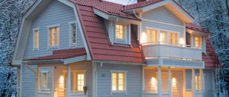
The installation of a broken attic roof allows you to get a full-fledged living space on the second floor
Features of the arrangement of the attic floor
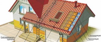
The installation of attic rafters must be done so that the frame provides maximum reliability, allowing it to withstand the weight of the roofing pie. At the same time, the rafter system must be light in order to reduce the load on the load-bearing walls of buildings.
For this reason, the main material for the construction of attic floors today is still wood that meets these requirements. In this case, ceramic or metal tiles and ondulin are used to cover roofs. These roofing materials allow you to create a reliable coating with excellent performance characteristics.
When arranging the attic floor, you need to remember that it should provide a higher degree of thermal insulation compared to other living spaces. At the same time, it is necessary to perform high-quality hydro- and vapor barrier.
Types of rafter systems
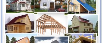
The main types of rafter systems for attic construction are presented in two options:
- gable;
- broken rafter system.
Photo gallery: what is an attic
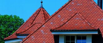
A sloping roof allows you to obtain the optimal combination of roof slope and usable area under it
It is possible to increase the volume of the attic in a structure under a gable roof only due to the high height of the ridge
The attic can be “equipped” with an external structure with a balcony under a separate roof
The balcony can be an integral part of the attic roof structure
However, in practice, the roofs of a country house are so diverse that it is almost impossible to classify them. The design uses a variety of elements:
- hip bevels;
- birdhouses;
- awnings;
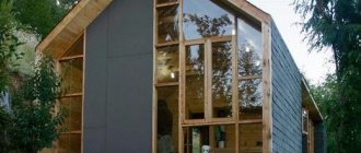
- semi-built-in translucent structures (greenhouses);
- lanterns and other architectural solutions in the most original and sometimes unexpected combinations.
Photo gallery: projects of houses with a gable roof and an attic
A gable roof can be decorated with an elegant “birdhouse”, which will also increase the area of the attic
In large houses, a gable structure can be used as one of the elements of the roof composition
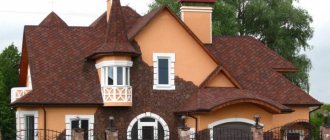
The main idea of such a house is to combine simplicity of execution with perfectly selected finishing elements
Elements and components of the attic roof rafter system
Obviously, the most durable structure is a gable roof. But to obtain a sufficiently spacious room with such a rafter arrangement, it is necessary to reduce the angle between the slopes, and this leads to an increase in wind loads on the roof. A reasonable solution is to create a semi-attic, when racks are installed from floor to ceiling to a height of 1.3–1.8 meters, and rafters are already attached to them. Such a device requires the installation of low crossbars to compensate for the thrusting loads from the rafter legs on the racks.
To increase the useful volume of the attic, the crossbars that form its ceiling are installed as close as possible to the ridge unit
The use of a sloping roof allows you to simplify the shape of the attic room and obtain a larger volume of living space.
The construction of a sloping roof allows you to get a much larger attic than the installation of a conventional gable roof
The main elements of the rafter system are:
- The supporting base is the Mauerlat. Its purpose is to distribute the loads from the rafters onto the wall.
- Rafter - a beam that takes the load from the roofing pie.
- Ridge beam - designed to absorb the load from the rafters in the upper part, often used for fastening and positioning rafters.
- Stand, jib, spacer. Additional details to enhance the load-bearing capacity of the rafters and compensate for the bending load on the rafters from the roofing pie.
- The bench is a support for the stand. Placed on translations.
- Translations are transverse beams that form the basis for the ceiling.
- Crossbar is a horizontally installed connection between opposite rafters, increasing their load-bearing capacity.
- Internal and external sheathing. It is stuffed perpendicular to the rafters.
In a simple gable roof design, some elements, such as crossbars and tie rods, may be missing
When installing a rafter system, additional parts are widely used to strengthen the fastening of structural elements.
The use of modern fasteners allows us to effectively strengthen the structure and significantly reduce installation time
Construction of a rafter system for a gable roof with an attic
The gable roof rafter system is based on a triangle - the most rigid figure.
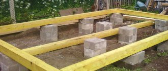
- Immediately after installing the Mauerlat, the transfers are installed and temporary flooring is made for convenience and safety when performing work.
- Roof trusses are installed, first of all - the outer ones, the gable ones. They consist of two rafters connected to each other by a top tie. During installation, the coincidence of the next rafter leg with the plane of the already installed nodes is checked. For this, a construction cord stretched between the gable posts is used. The rafter legs are temporarily attached to the mauerlat.
First, the outermost trusses on the side of the gables are installed - After installing the last rafter truss, two purlins are placed perpendicular to the plane of the rafter legs in the corners of the base of the triangle formed by the beams and the tie. These structural elements are already firmly attached.
- At the four extreme points, racks are installed, resting on a beam, the purpose of which is to distribute the load from the rafter leg to the interfloor ceiling through the racks. These details indicate the outline of the attic space.
- Next, the final fastening of the skeleton of the rafter system is carried out. The rafters can be fastened to the mauerlat with metal corner plates using bolts or long self-tapping screws.
After installing all the rafters, they are finally fastened at the joints with the Mauerlat and the ridge - If necessary, braces are installed between the bases of the racks and the rafters.
Only the main elements of the rafter system are listed. Additional parts can be used to increase the strength of the structure.
The procedure for calculating rafters
A competent and accurate calculation of the mansard roof rafter system will allow you to build a strong and reliable structure that can last for many years.
When performing calculations, take into account:
- weight of attic elements;
- wind and snow loads.
Since these indicators vary in different climatic zones, the design of the rafter system of roofs with an attic can differ significantly. The method for calculating rafters when creating layered structures is simpler than hanging ones. In some cases, roofers use combined options for arranging the frame.
When an attic is to be built, it is advisable to entrust rafter drawings and complex calculations to professionals with extensive experience in such work. The fact is that when performing calculations, mathematical formulas and different coefficients are used.
By calculating the weight of the roof, they find out the magnitude of the load, which is expressed in kilograms per “square” of the truss structure. Typically, the average value of this parameter for residential buildings is about 50 kg/m².
Calculations of wind and snow loads in regions with unfavorable climatic conditions indicate that rafter systems for gable mansard roofs should be made with paired rafters and continuous sheathing - they will avoid frame deformations.
Installation of the roof truss system taking into account the formation of the attic
The rafter system of a gable roof can be formed in two ways:
- Assembly of the main structure below, followed by lifting to the ceiling and installation on the mauerlat.
- Installation of rafter legs in detail directly at the installation site.
The first option is a more productive and convenient way.
Assembling the roof trusses below
This work is done in the following order:
- It is necessary to make a simple slipway for assembling trusses. The only requirement for it is the location of the supporting elements of the rafters strictly horizontally.
- The details of the first truss must be completed according to pre-prepared drawings. It is a collection of a minimum set of basic parts that ensure structural rigidity.
- Assemble the first truss and install additional fasteners.
- The production of subsequent trusses is carried out using the first one as a template, the parts are made on site. For accuracy and full compliance, the parts of each subsequent truss must be secured to the template with clamps. When ready, the farm is removed to the side.
All roof trusses are made according to a single template, which is the first assembled structure - Then the trusses are lifted up one by one and installed in their place.
- The outer gable trusses are installed first, then all subsequent ones. The rafters are positioned in one plane using a construction cord stretched between the gable trusses.
Video: assembling roof trusses “on the ground”
Installation of rafter elements
The rafters, as the main load-bearing element of the roof skeleton, must be securely connected to each other. Many different methods have been invented for this, including specific ones designed for certain types of buildings. The rafter system of a wooden house requires special attention. The beam is attached to the Mauerlat by a sliding device, and the ridge connection is made on a hinge. This is due to constant seasonal movements of the log house, which must be compensated.
Photo gallery: methods of connecting rafter legs
The rafter legs are attached to the mauerlat using metal corners
The rafters are connected at the ridge end-to-end or through a gash
Critical nodes of the rafters are connected using metal connecting plates
The rafter legs are connected using special hinge joints, ensuring freedom of movement of the structure during seasonal deformations of the building
The joint in the ridge can be reinforced with bolts
Installation of support posts and purlins
This is a responsible operation, because at this stage the surface of the front finishing of the walls and ceiling of the attic is formed. Therefore, the execution procedure is the same as when installing rafters:
- The racks are installed first on the gables with the lower part resting on the mauerlat. They form the outline of the attic room. The racks are cut from timber: in the lower part at a right angle, in the upper part - at the angle of inclination of the rafter leg. The stand is installed inside the rafter leg and attached with metal plates to the rafters and the mauerlat. They are fastened with self-tapping screws 45–50 millimeters long.
The racks are attached to the purlins and the Mauerlat using metal corners - The bed is laid on top of the transfers.
- The cords are stretched along the entire length of the attic room. On four installed racks, nails are driven into the ribs and two cords are pulled between them.
- Intermediate posts are cut from timber at the installation site so that their ribs are located along the cord. The racks are fastened using plates in the upper part and corners in the lower part. For each post you will need two plates at the top and two corners at the bottom.
- The racks are installed under each rafter with an emphasis at the bottom on the support. The upper part of the post is attached to the tie rods.
- Then purlins are installed with fastening to the rafters. They need to be brought inside the triangle formed by the ties and the rafter legs and secured to the rafter legs with nails 125–150 millimeters long at four points at each intersection.
For the manufacture of all parts of the rafter system, timber of the same dimensions is used, usually measuring 50x150 or 40x150 millimeters.
Video: quick installation of the rafter system
Lathing
This is a mandatory element of the rafter system. In the case where a warm attic space is formed in the under-roof space, the sheathing is done twice:
- External sheathing is used to secure the finishing roof covering. In addition, if each board is attached to the rafters with two nails, it serves as a fastening element of the frame. In addition, an insulating and moisture-proof roof pie is formed under the sheathing.
- The internal sheathing serves as a frame for insulating the attic and installing the final finishing of walls and ceilings.
In addition, counter battens are also installed, with the help of which the ventilation system of the under-roof space is organized.
The counter-lattice is placed parallel to the rafters and provides clearance for ventilation of the under-roof space
For the lathing, a board measuring 25x100 millimeters, edged or unedged, is used. Unedged boards must first be sanded. It is not recommended to use a board wider than the specified size. When warping, it can deform the finishing coating or damage the roofing pie.
The sheathing boards are fastened with nails at least 70 millimeters long and at least two nails for each intersection. This method increases the structure’s resistance to wind loads.
The spacing of the sheathing depends on the material of the finishing coating - for ceramic tiles and soft roofing it should be minimal (about five centimeters); for metal tiles or corrugated sheets, a distance between the boards of up to 70 centimeters is allowed.
A properly laid roofing pie must contain a ventilation gap between the insulation and the roofing material, which helps quickly remove moisture
Calculation of a sloping roof
The calculation is carried out taking into account the type of main roof covering, as well as the angles of inclination of the rafters. Calculating the required volume of covering material for a sloping roof is simple:
- measure the length and width of the slopes, multiply to obtain the area of each slope;
- sum up the calculated areas and divide the resulting result by the area of the roofing (metal tile sheets, ondulin, etc.) + 10–15% for overlap and margin.
Insulating materials are calculated similarly.
Before calculating the rafter system, you need to draw up a house plan and look at maps of snow loads and wind loads by region. Anyone who is familiar with ArchiCad or SolidWorks and knows the basics of construction can create a project for the roof of their house in these programs, where all elements have weight and size. Based on this, you can immediately draw up an estimate and find out what the costs will be for arranging the selected roof.
Video: roof truss system, design in ArchiCad and SolidWorks
We draw a sketch of the house on a checkered piece of paper, where we display the features of the sloping roof rafter system - shape, width of the wall, slope angles, etc. Let's take a sketch from a photograph as an example.
When drawing up a house diagram, it is necessary to maintain proportions
Starting data: the width of the wall on which the roof end is formed (Vd) is 6.4 m, built, for example, in Tyumen, the height of the box according to the sketch is 2.3 m, the distance from the ceiling to the roof ridge is 3.5 m, the angles of the slopes are angle a 60° between the ceiling and the slope and angle b at the break point of the slopes is 30°, the desired height of the room (Nm) is 2.5 m, there is no extension of the floor beams beyond the wall (Вв), the pitch of the rafters will be taken equal to 0.6 m.
We find the location of the construction on the map and find out the amount of snow loads for the given area. Moreover, if construction is carried out on the border of regions, then a larger value is preferred. In our example, the snow load (Tyumen) is 180 kg/m².
The amount of snow loads is determined depending on the terrain
We determine the value of the wind power from the wind load map and multiply it by the correction factor (k) from the table below, since the type of terrain and the height of the future building matter here. In our example, the wind load for Tyumen is 24 kg/m², k 0.65 (column “B”). In total we get 24 x 0.65 = 15.6 kg/m².
Using the wind load map, wind power is determined for all regions
Table: coefficient (k) for terrain types
| Building height, m | And the open coasts of lakes, seas, reservoirs, steppes, deserts, forest-steppes, tundra | B forested areas, urban areas and other areas evenly covered with obstacles more than 10 m high | In urban areas with dense buildings with a height of more than 25 m |
| no more than 5 | 0,75 | 0,5 | 0,4 |
| 5–10 | 1,0 | 0,65 | 0,4 |
| 10–20 | 1,25 | 0,85 | 0,55 |
If the house is being built within the city limits, but near the sea, then take the value of column “A”.
In our example, the value of column “B” is taken - the height of the house is over 5 m and it is being built within the city limits (Tyumen) in a cottage village where there are no high-rise buildings.
Video: sloping roof with attic, part 1 - design diagram, loads, DCS
We carry out calculations.
- We calculate the dependence of the width of the attic on the steepness of the attic slope (angle a) according to the laws of geometry - Vm = Vd - {2 x (Nm : tq a)} = 6.4 - {2 x (2.5 : tq 60°)}= 3 .51 m. The calculation was made without removing the beams, when the rafters rest on the mauerlat. With the removal of the floor beams outwards, say, by 0.5 m, the width of the attic room will increase to 4.01 m. Hence the conclusion - the greater the removal of the floor beams, the wider the attic room can be made.
- We calculate the total height of the roof: Nm + Hk (height of the ridge triangle), where Hk = 0.5 x Bm x tq b = 2.5 m + (0.5 x 3.51 x tq 30°) = 2.5 m + 1.01 m = 3.51 m.
- We calculate the length of the rafter legs: to calculate the lower rafter legs Nm: sin angle a = 2.5: sin 60° = 2.89 m length of the rafter leg; to calculate the ridge rafter Hk: sin angle b = 1.01: sin 30° = 2.02 m. If the structure is formed with the removal of the floor beams, i.e. the roof overhang is formed due to the extension, then the calculations of the rafter legs are completed. If there is no extension of the beams, then the rafters will need to be extended, which means that additional calculations need to be made.
- We calculate the elongation of the rafters - the working length of the filly - for the planned amount of the eaves overhang according to the formula - the desired length of the eaves overhang (k): cos angle a = 0.5 m, for example: cos 60° = 1 m.
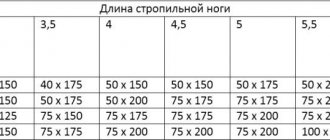
- We find out the slope of the slopes and the amount of load on the rafters, guided by the table “Recommended slopes of pitched roofs” located below.
- We calculate the load on the rafters. To do this, we will use the initial and calculated data. Load due to the slope of the slope (for example, a metal-tiled roof) + snow load, according to the snow load map + wind load (determined from the map adjusted by coefficient). Total: 5 kg/m² + 180 kg/m² + 15.6 kg/m² = 200.6 kg/m² x specified rafter installation pitch (we have 0.6 m) ≈ 110 kg/linear meter.
Table: recommended slopes of pitched roofs
| Roof covering material | Roof slope | Weight per 1 m², kg |
| Metal tiles | from 1:5 and more | 5 |
| Cement tiles | from 1:5 to 1:0.5 | 45–70 |
| Ceramic tiles | from 1:5 to 1:0.5 | 50–60 |
| Galvanized sheet with single seams | from 1:4 and more | 3–6,5 |
| Double folded | from 1:5 and more | 3–6,5 |
| Soft (flexible) tiles | from 1 : 10 and more | 9–15 |
| Corrugated sheets of cellulose-bitumen | from 1 : 10 and more | 6 |
| Corrugated sheets a/c medium profile | from 1:10 to 1:2 | 11 |
| Reinforced profile | from 1:5 to 1:1 | 13 |
Knowing the magnitude of the load, you can correctly select the cross-section of rafter lumber.
Table: relationship between load and beam thickness for the rafter system
| Load on rafter leg, kg/linear meter | Thickness of the board (timber), mm |
| 75 | 40 |
| 100 | 50 |
| 125 | 60 |
| 150 | 80 |
| 175 | 100 |
Note: when choosing a load, round up.
Video: sloping roof with attic, part 2 - calculation in Scad, selection of sections of roofing elements
When purchasing lumber, you need to take into account the insulation, as well as the ventilation gap and the vapor-proof layer of the roofing “pie” (which is 20–30 mm).
The calculation of a sloping roof is voluminous, but simple. You can do it yourself manually or using the Scad calculation program. You can also use the online calculator for calculating the rafter system on construction sites, where you need to enter the requested data and receive a ready-made calculation.