One-story houses
Photo: trendir.com
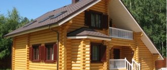
The project of the original small cottage in the photo was implemented on the island of Terschelling in the Netherlands. This is a summer house made of cedar beams, designed for relaxation by the sea. It stands out against the backdrop of the dunes with its very unexpected design. This type of architecture is a good example of how the topography of the landscape determines the height of the house - the sea should be visible from the attic windows.
The small summer house in the photo is a wooden architecture originally from Austria. The building is “dressed” in wood from the tip of the roof to the ground - the plank cladding of the facades extends to the roof and looks very unusual. The cottage's gable roof has no overhangs and perfectly completes its minimalist appearance.
Photo: Chartered Architect
The most common version of a wooden prefabricated house in Scandinavian countries is a cubic-shaped cottage with a gable roof and a glazed pediment.
Photo: trendir
Two slopes with different slopes are a rational solution for a small frame house with an attic, allowing you to illuminate the attic space and organize a full-fledged bedroom or children's room there.
Photo: Painted Rusted Roofing
The gable seam roof is organically woven into the design of private houses, bathhouses and gazebos in country style, sheathed with colorful rustic boards.
Another example of architectural harmony is a one-story log house under a colorful seam roof with fragmentary rusting, made in production conditions.
See also: Cottage interior design: 60 photos in a modern style
Main types of roofs
All roofs can be divided into two main types:
- flat;
- pitched.
Flat roofs
Multilayer horizontal structures with virtually no slope, 1-2⁰ (up to 4⁰) required for precipitation removal are visually almost invisible. They are divided into exploited and non-exploited, relevant for houses in a modern and minimalist style. Despite the apparent simplicity of the design, the complexity of implementation is due to increased requirements for waterproofing.
Pitched roofs
Within the categories, they are divided into several varieties, differing in the number and geometric shape of the slopes and the level of complexity of implementation.
- A pitched roof is the most simplified subtype in the original version, represented by one inclined plane supported by load-bearing walls located at different height levels. The slope angle of the slope varies in the range from 10 to 60⁰; the optimal slope of a pitched roof is 30-35⁰. To increase the decorative effect of a pitched roof, the design is made more complex by slightly rounding, bending the plane or combining orientation.
- A gable (gable) roof is one of the most common structures; it consists of two inclined planes separated by a ridge (rib). In this type of construction, pediments appear - the side parts of walls in the form of triangles, formed from the main wall materials or other than them. Depending on the architectural design, the slopes can be either identical, forming an isosceles triangle in diameter, or with different angles of inclination and overhang length. The minimum permissible angle of inclination of the slopes is 20⁰, the optimal is 40-60⁰.
The remaining subtypes, with the exception of non-standard designs, are a derivative of the gable roof.
Pil18Super-Moderator FORUMHOUSE
Hip-slope (hip or hipped) roofs are formed from gable roofs. Their pediments are cut off by inclined planes to their full height. The triangular slopes of hipped roofs are called hips. Semi-hip roofs differ from hip roofs in that only part of the gables are cut off by inclined planes. Four-gable roofs are formed from the connection of four gable planes.
If it is not an attic that is planned under the roof, but a living space for seasonal or year-round use (heated), an attic-type roof is built. It can be either a simplified gable, or a hip, or half-hip; its feature is not the shape of the slopes, but the presence of thermal insulation in the roofing pie. Often, if there is a lack of living space, a cold attic is converted into an attic or a major reconstruction is carried out, adding an attic roof with a larger square footage.
The original roofs include round ones (dome, conical) - they are erected mainly on round-shaped houses, as well as over turrets, on houses with “castle” architecture. They differ from ordinary pitched ones not only in shape, but in the special structure of the rafter system.
Two-story houses
The versatility of a gable roof lies in the fact that it can complement the architecture of a house built from any material: wood, brick or concrete.
Photo: proroofingsv.com
For private estates that include several buildings, multi-level gable roofs with the same slope are best suited.
The gable roof of the main house can be combined with the hip roof of an extension - porch, veranda, terrace or garage.
See also: Hip roof: 65 photos of private houses
Installation of roofing material
The method of laying roofing material, first of all, depends on the type of composition used (tiles, corrugated sheets, other type of roofing). Installation work is carried out strictly from the bottom up, always using special gaskets for additional shock absorption.
Thus, installing a gable roof with your own hands is quite easy using step-by-step instructions and training video lessons.
Ultra-modern gable roofs
Photo: homedit.com
The architecture of the one-story house is created on a contrasting combination of ultra-modern metal frame with continuous glazing and reed roofing. Metal beams seem to grow from under the thatched roof and symbolize the symbiosis of progress and tradition.
Photo: contemporist
The originality of the modern cottage in the photo lies in the absence of any covering on the gable roof. Both the walls and the roof of the house are cast from monolithic concrete. An interesting detail of the architectural concept is the square and rectangular slots in the roof slopes, which provide access to light onto the balconies and terraces.
Photo: Daily TV-Shows for You
Rusty metal in the design of the house in the photo is not a sign of neglect of the building, but a stylish trend of recent years that came to us from America.
The cascading roof project in the photo was created on the basis of a gable structure and implemented using artificially aged corrugated sheeting.
See also: Beautiful interiors of cottages: 60 photos inside country houses
How to make a gable roof: step-by-step instructions with photos
The work includes several stages:
- preparation;
- installation of a rafter system;
- laying hydro-, heat- and vapor barriers;
- installation of roofing material.
Lumber must be well dried. They are stored in stacks under a canopy or covered with film or tarpaulin in bad weather.
Preparation
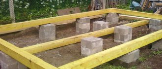
If the walls are made of piece materials - blocks, bricks - it is recommended to install a reinforced concrete belt around the perimeter of the building. This will allow you to assemble the structure together and level the surface for laying the Mauerlat.
At the same stage, studs with a cross section of 10 mm made of galvanized steel are embedded in the fresh solution. You need to start from the corners, the laying step is 60 cm. Subsequently, the Mauerlat will be placed on them and secured with nuts.
To prevent contact between wood and concrete, waterproofing is installed - the surface of the reinforced belt is coated with hot bitumen and covered with 2 layers of roofing material.
Laying the Mauerlat
Holes are drilled in the timber in those places where the studs protrude from the walls. The Mauerlat is laid on the surface of the wall closer to its inner side to avoid demolition during strong winds.
The bars need to be aligned horizontally. You can insert spacers or trim off protruding parts.
It is allowed to lay the Mauerlat not entirely on the wall, but in separate segments directly under the rafters. For brick or concrete walls, fastening with metal plates, wooden plugs and brackets, and curved reinforcement is additionally used.
The length of the beam is joined with an oblique or straight lock. Corner joints are sawed into place and secured to the wall with anchors (studs).
Installation of ridge beams
At the highest points of the roof, a purlin is laid, which is attached to the posts and beams with metal corners and plates. The pitch of the racks is 3-5 m.
You can change the sequence and start by installing rafters at the ends of the building, but then you will have to secure each pair of beams with braces or boards. In the case where there is a ready-made run, the assembly proceeds faster and with better quality.
Installation of ridge beams
Installation of rafters
It is better to prepare rafters using a template. A groove is cut in the lower part to rest on the Mauerlat. The depth of the cut is no more than 1/3 of the width of the board.
2 types of fastening rafters to the Mauerlat
If lumber has to be spliced for rafters, an overlapping or overlay joint is used. It is recommended to make the joint at a distance of at least 1 m from the support points, preferably at about 1/3 of the rafter length. It is impossible to connect the boards in the center, since the maximum bending moment acts in the middle, and the beam can bend at the weakest point.
The assembly of the rafters begins from the gables. First, the first and last fragments are set, then the cord is pulled and markings are made. The studs should not fall into the support areas, so as not to create problems with cutting. Read in detail about attaching rafters to the mauerlat in a separate article.
The rafters are secured to adjacent elements using stops, struts and ties. It is important to firmly fix the system in space.
Fastening the sheathing
The base for laying the roofing covering is made of boards, slats, OSB boards or moisture-resistant plywood. The choice of material depends on the type of coating:
- for metal tiles - boards with a pitch of 35-45 cm, equal to the length of the transverse wave;
- flexible tiles, ondulin, roll roofing - continuous flooring;
- asbestos-cement slate - lathing in increments of 450-750 depending on the angle of inclination.
Boards or slats are laid perpendicular to the rafters. At each fastening point they are screwed with two self-tapping screws. The lathing additionally gives the rafter system rigidity and stability.
broken roofs
Broken gable roofs are usually used if the cottage design includes a balcony, porch or veranda. In this case, one of the slopes turns into a flatter plane above the extension.
Broken roofs of bright colors are colorfully combined with the rustic style of houses built from logs and timber.
Gable hip roof
A gable hip roof is also called a half-hip roof - it has truncated slopes and is optimally suited for regions with difficult weather conditions: heavy snowfalls, showers, winds.
An important feature of half-hip and hip roofs is the complex design of the rafter system, which significantly increases the cost of building a private house, especially if it has a complex layout, as well as extensions, bay windows, and balconies.
Hip roof rafter system: features and calculator
Hip roofs are becoming increasingly popular among owners of private houses. This is not surprising, since such a scheme is distinguished by a number of undeniable operational advantages, and in addition, it looks very original, giving the house a special aesthetics.
Hip roof rafter system
Some do-it-yourself homeowners may be put off by the fact that the hip roof truss system looks overly complicated. Yes, it is certainly not as simple as a single-pitch or regular gable gable roof. Nevertheless, this rafter system is completely subject to the laws of geometry, and it is quite possible to make a preliminary calculation. Installation, of course, will require some experience in carpentry, but with good helpers, or even better, with a qualified consultant, you can take on this large-scale undertaking.
What are the advantages of a hip roof?
Agree that the hip roof looks very attractive. But the aesthetics it gives to the building is by no means the main advantage of such a structure.
The aesthetics of a hip roof are certainly important, but its advantages are not limited to this
- The complete absence of vertical planes makes such a structure highly vulnerable to wind loads. If the slope of the slopes is also insignificant, the parameter of wind pressure on the rafter system was reduced to a minimum.
- The “smoothness” of the shapes on all four sides makes such a roof generally resistant to all types of precipitation.
- From an energy saving point of view, a hip roof is far superior to a gable roof.
- It is much easier to insulate such a roof by placing a thermal insulation “pie” under the roof slopes. A gable roof always has two problematic gables that require a special approach to insulation and perfectly “catch the wind.”
- Successful distribution of loads, due to the peculiar arrangement of the main, diagonal (corner) and hip rafters, ensures high resistance of the entire system to deformation under the influence of external forces.
- Finally, a hip roof can also serve as an attic (at certain slope angles, of course). A roof window can crash into any of their slopes.
The disadvantage of such a system is the relative complexity of the design. In addition, on small buildings and at low roof slope angles, the attic space becomes insufficient and unsuitable for useful use, especially if the rafter system requires additional reinforcement with struts, racks, etc.
Obviously, the shortcomings are quite conventional, and they can be minimized. But the number of advantages is impressive, which contributes to the constant growth in popularity of hip roofs.
Main design features of a hip roof
So, what is a hip roof from a structural point of view?
This is a hipped structure. The two slopes running along the long side of the building have the shape of a trapezoid, the upper side of which is a ridge, and the side ribs diverge from it to the corners of the building. On both gable sides, the slopes have the shape of an isosceles triangle, whose apex rests on the extreme point of the same ridge.
This is what a classic hip roof looks like
Now, if you virtually carefully remove the roof covering from the roof and remove the walls of the house so that they do not interfere with the view, then something like this will be revealed - actually. The wooden structure of the hip rafter system itself.
Basic diagram of a hip rafter system.
Now let's get acquainted with the most basic structural elements of the hip rafter system.
The main elements of the hip roof rafter system
1 – Mauerlat – a powerful wooden beam fixed around the perimeter of the upper end of the walls of the house. It is the basic basis for installing the truss structure.
2 – ridge beam (purlin). It should be located strictly along the longitudinal axis of the house, at a height from the floor level, depending on the planned steepness of the roof slopes.
3 – central main rafters. They are located with the calculation of support on the mauerlat and on the edges of the ridge girder. There are 4 such rafters in total, two for each side slope.
4 – central hip stops. They are located strictly along the ridge axis, dividing the triangular hip slope exactly in half. The total quantity is two pieces.
5 – corner or diagonal rafters (otherwise – slanted legs). They rest on the corner of the mauerlat and on the end of the ridge girder. The longest of all rafter legs. Total quantity – 4 pieces. Thus, at each end of the ridge, five rafters converge - two main central, one central hip and two diagonal (sloping).
6 – intermediate rafters. They are installed on the side slopes between the central rafters, have the same size, and rest in the same way - on the Mauerlat and on the ridge girder. The quantity depends on the selected installation step. With a short length, the ridge may be completely absent.
The ridge on this hip roof is so short that there is simply no need for intermediate rafters
7 – shortened rafters. They are installed along the side trapezoidal slopes between the central rafters and the corner of the roof. They rest on the mauerlat and on the slanted (diagonal) legs. The quantity depends on the installation step. The length of the parts changes - it decreases as it approaches the corner of the system.
8 – shortened rafters of the hip slope (springs). The location, number and dimensions are generally similar to those with shortened side rafters.
This was shown the simplest, basic version of a hip rafter structure. In practice, when a roof is erected over a residential building, one has to resort to reinforcement, that is, the installation of additional elements:
Hip roof reinforcement elements
9 – racks supporting the ridge girder. They can rest on a beam laid exactly in the center of the ceiling parallel to the ridge (for example, if there is a solid internal wall below). Another option is to rest the racks on the floor beams or on the tie rods (crossbars) connecting pairs of rafter legs.
10 – tie rods (crossbars), which can simultaneously serve as floor beams. Another option is actually beams embedded in the mauerlat or embedded in the walls of the house. The puffs can be located higher, closer to the ridge girder. Often in this case it becomes the basis for lining the attic ceiling. The ties or beams become the basis not only for the racks, but also for some other reinforcing structural elements.
rafter mount
11 – if the main or intermediate rafters are too long, more than 4.5 m, then they must be strengthened by installing diagonal struts that rest against the purlin located below or against the floor beams (tightenings). The struts are usually installed at an angle of 45 ÷ 60°, and the use of such intermediate supports makes it possible to reduce the cross-section of lumber used to make rafter legs.
12 – diagonal rafters (sloping legs) are always the longest. As a rule, they first of all need strengthening, since they will serve as support for a number of shortened rafters (springs). One option is to install a truss, as shown in the figure. An angular truss beam is installed, which cuts into the mauerlat, and from it a vertical post goes to the bevel leg. Another option for strengthening the diagonal rafters is the same struts, which will rest on the central beam from below.
13 – wind beam, which is nailed obliquely from the inside to the rafters, usually on the windward side of the building. It is also used on both sides when a house is being built in a windy region and the wind direction is unstable.
14 – to form eaves overhangs, you can increase the length of the rafter legs so that they extend beyond the external walls to a certain distance. This, however, is not always possible or justified - due to restrictions on the standard length of lumber or for reasons of economy. The solution is to use parts that extend the rafters, fillets, which will form a cornice overhang of the required width from the level of the walls of the house.
How are the elements of a hip rafter system calculated?
So, the most important stage lies ahead - to design the future hip truss structure. In this matter, a certain sequence should be followed.
Selecting the roof slope angle and determining the height of the ridge
You should start by choosing the optimal roof slope angle. In principle, the angle of the side and hip slopes may differ, but still the “classic” option is their identical slope: this way the loads are distributed evenly, and the roof will look more advantageous in appearance.
For hip roofs, a slope angle of 20 to 45 degrees is usually accepted. In regions with increased snow load, it makes sense to make the slope steeper, and where wind pressure prevails, it would be optimal to give a slope of no more than 30 degrees. However, this is the owner’s decision, since plans for using the attic space can also play a role.
An important parameter for choosing the slope angle is the planned roof covering - for its various types there are certain lower limits of steepness. Below is a diagram of roof slopes (in degrees and percentages). The diagram is made with exact adherence to scale, so that, if desired, you can use it to set the angle in proportion (the ratio of the height of the rise to the length of the base of the rafter triangle).
wood screws
Diagram of roof slope angles and permissible minimum slopes for various types of roofing
The arrows show the lower slope limits for various types of roofing. The first three points do not interest us in this case - they relate to flat roofs.
| № | Slope amount | Type of coating used (minimum slope level) |
| 4 | ≈ 9° 1:6.6 or 15% | Rolled bitumen materials - at least two layers glued to mastic using a hot method. The use of certain types of corrugated sheets or metal tiles is allowed (in accordance with the parameters established by the manufacturer). |
| 5 | ≈ 10° 1:6 or 17% | Asbestos-cement wave slate with reinforced profile. Euroslate (odnulin). |
| 6 | ≈ 11÷12° 1:5 or 20% | Soft bitumen shingles |
| 7 | ≈ 14° 1:4 or 25% | Flat asbestos-cement slate with reinforced profile. Corrugated sheets and metal tiles. |
| 8 | ≈ 16° 1:3.5 or 29% | Metal roofing with seam joint. |
| 9 | ≈ 18÷19° 1:3 or 33% | Asbestos-cement wave slate of regular profile |
| 10 | ≈ 26÷27° 1:2 or 50% | Natural ceramic or cement piece tiles, composite polymer concrete, slate tiles. |
| 11 | ≈ 39° 1:1.25 or 80% | Roof covering made of shingles, wood chips, natural shingles. Reed roofing |
There is one more nuance. A hip roof, as we have seen, assumes the presence of trapezoidal and triangular slopes. When using sheet roofing, considerable losses of material during cutting will inevitably occur - it can reach up to 30%. The optimal option seems to be with soft bitumen shingles or using piece roofing materials. However, again, everything is decided by the owner of the house.
Once the slope angle of the slope has been selected, it is easy to determine the height of the ridge to which the central and intermediate rafters will converge.
Determining the height of the hip roof ridge
We know the width of the house D. The ridge is located strictly along the longitudinal axis, that is, at a distance d = D/2. on the angle α . The height of the ridge is thus determined by the following relationship:
h = d × tan α
In order not to force the reader to waste time searching for a table of tangents, below is a calculator for calculating the height of the ridge.
Go to calculations
Ridge purlin length
We determine the length and location of the ridge beam (purlin).
Since it is assumed that the slope angle on the side and hip slopes will be the same, then the length of the central rafters should also be the same. And this, in turn, means that the edges of the ridge purlin should be located from the end walls of the house at the same distance as the purlin itself from the walls parallel to it.
“Classic” ridge girder arrangement
1 – Mauerlat
2 – ridge run.
3 – central side rafters
4 – central hip rafter, equal in length to the central side rafters.
This means that the length of the ridge beam is equal to the length of the house minus 2 d , and if simplified, then the length of the house minus its width D. It should be located strictly in the center, along both longitudinal and transverse axes.
To make the ridge purlin, the same material is usually used as for the central rafter legs. Vertical posts for its installation are cut taking into account the width of the beam, so that when assembled, the upper edge of the ridge is located at the calculated height h .
Ridge girder on posts reinforced with diagonal struts.
It is advisable to strengthen the ridge frame resting on the bed with diagonal struts, as shown in the figure.
Length of central rafter legs
Once the installation height of the ridge girder and its distance from the mauerlat (in horizontal projection) are known, it is quite possible to immediately calculate the length of the central rafters.
Determine the required length of the central rafters
Here everything is extremely simple. Using two known legs - height h and base d, it is easy, using the Pythagorean theorem, to find the hypotenuse, which will become the length of the rafter leg L from the ridge to the mauerlat. Use the built-in calculator for this:
Calculator for calculating the length of the hypotenuse (rafter leg) using known legs
It is clear that the intermediate rafters, which also rest on the ridge girder, will have exactly the same dimensions.
Trimming rafter legs for connection at the ridge part
To connect the rafters on the ridge girder, they can be cut at an angle β, which is equal to:
Β = 90° - α
The rafter legs are adjacent on both sides to the ridge girder
The method of connection, however, can be different, for example, overlapping the rafter legs with the placement of the ridge girder at the bottom - this is taken into account when calculating the size of both the rafters themselves and the height of the posts for the ridge girder. It is assumed that the highest point of the ridge in this case is formed by the upper intersection of the rafter boards.
Fastening the rafter legs above the ridge purlin.
The lower edge of the rafter legs rests on the mauerlat. Options are also possible here, but we will not consider them in this publication, because this is well described in other articles.
Mauerlat - a reliable basis for the rafter system
If on a single-pitched or gable roof the mauerlat can only be attached from the side of the roof slopes, then with a hip system it must be a closed frame. How to install the Mauerlat is in a separate publication on our portal. And another article is devoted to the basic rules for attaching rafters to the Mauerlat .
You can immediately decide how much it is necessary to lengthen the rafters, if they are the ones that will form the eaves overhang. In the case when the cornice is created by fillies, the resulting value will become “useful” from the length, that is, it will be useful in any case.
Calculation of the length of the rafter extension (working length of the fillies) to form the eaves overhang
If the planned width of the eaves overhang k and the roof slope angle α , then the parameter Δ L can be easily determined using the formula:
Δ L = k / cos α
Calculator for calculating the elongation of rafters for eaves overhang
Now, to find out the total length of the rafter leg, all that remains is to sum up the obtained values L and Δ L.
This extension will be the same for all rafters and soffits, with the exception of diagonal rafters (sloping legs). The calculator provides a special calculation for them.
Length of diagonal rafters
These rafter legs are the longest and will experience the maximum load.
Diagonal rafters or sloping legs are the longest of all
Determining their length is not difficult. You can again use the Pythagorean theorem, that is, resort to the help of the calculator located above. The diagonal rafter is a hypotenuse with a base equal to half the building's width d length of the central hip rafter L.
Right triangle with hypotenuse - diagonal rafter
Ld = √ ( L² + d²)
The amount of elongation of the rafters to form the eaves overhang is somewhat different, as we saw from the calculator presented above.
Installation step of rafters and their cross-section
The linear dimensions of the central, intermediate and diagonal rafter legs are known. Now you need to decide on the cross-section of the board (timber) for their manufacture and the installation step. These values are interrelated and depend on the expected loads on the roof structure.
It's time to decide on the cross-section of material for the rafter legs and the installation step of the intermediate rafters
The total load, expressed in kilograms per square meter, is the sum of several quantities. This is, first of all, the weight of the roof structure itself, taking into account the roofing material, sheathing, insulation, etc. To this are added temporary loads - the pressure of fallen snow and wind influence. In addition, natural loads that are difficult to predict are also likely - hurricane winds, seismic shocks and other force majeure phenomena. In this regard, a certain strength reserve is introduced into the roof structure.
The load falling on the roof is distributed along the rafter legs. The more often they are mounted, that is, the smaller the step of their installation, the less falls on each linear meter of the rafter leg, and the smaller the cross-section of lumber can be. The second parameter that affects the cross-section of the material is the span of the rafter leg, that is, the distance between two points of support.
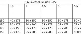
Below is a table that will help you determine the required cross-section of timber for the rafter legs. How to use it?
screwdriver
The initial value is the value of the distributed load on the rafter leg (with an intermediate value, the next one is taken in a larger direction). In this column, find a cell with the length of the rafter span. This cell predetermines the line in which, on the right side of the table, the required sections of timber for the manufacture of rafter legs are indicated. Please note that, if desired, you can also use round timber - the table shows the values of the required diameter.
| Estimated value of distributed load per 1 linear meter of rafter leg, kg/m | Section of lumber for making rafter legs | |||||||||||
| 75 | 100 | 125 | 150 | 175 | from a board (timber) | from round timber | ||||||
| board (beam) thickness, mm | diameter, mm | |||||||||||
| 40 | 50 | 60 | 70 | 80 | 90 | 100 | ||||||
| Planned length of rafters between support points, m | board (beam) height, mm | |||||||||||
| 4.5 | 4 | 3.5 | 3 | 2.5 | 180 | 170 | 160 | 150 | 140 | 130 | 120 | 120 |
| 5 | 4.5 | 4 | 3.5 | 3 | 200 | 190 | 180 | 170 | 160 | 150 | 140 | 140 |
| 5.5 | 5 | 4.5 | 4 | 3.5 | — | 210 | 200 | 190 | 180 | 170 | 160 | 160 |
| 6 | 5.5 | 5 | 4.5 | 4 | — | — | 220 | 210 | 200 | 190 | 180 | 180 |
| 6.5 | 6 | 5.5 | 5 | 4.5 | — | — | — | 230 | 220 | 210 | 200 | 200 |
| — | 6.5 | 6 | 5.5 | 5 | — | — | — | — | 240 | 230 | 220 | 220 |
For example, with a distributed load on the rafter leg of 150 kg/m and a span length of 5 meters, a beam of one of the sections will be required: 70 × 230; 80×220; 90×210 or 100×20, or a log with a diameter of 200 mm.
Now - how to calculate the distributed load on the rafters. For this, there is a special algorithm that takes into account the main factors influencing the rafter system. In this publication, we will not present the entire cascade of formulas and coefficients, but will suggest using a calculator in which these physical and mathematical relationships are already included.
Calculator for calculating the distributed load on rafter legs
For the calculation you will need several initial quantities:
- The angle of the roof slope is already known to us.
- The planned type of roofing - the constant weight load on the rafter system depends on this.
- The snow load value for a given region is included in the calculator in accordance with the zone, which can be determined from the presented schematic map:
Distribution of the territory of the Russian Federation according to the degree of snow load
- Wind exposure level. Also determined by the zone according to the schematic map presented below:
Distribution of the territory of the Russian Federation into zones according to wind pressure levels
- Height of the building in ridge.
- The degree of openness of the construction site. The calculator indicates the main features for determining the zone, but it should be borne in mind that the presence of the specified natural or artificial barriers to wind can only be taken into account if they are located no further than 30 × H, where H is the height of the building in a skate.
Finally, the rafter installation step. This value can be changed by selecting the optimal value of the distributed load. It is customary to take into account that if the roof is insulated, it is recommended to coordinate the installation step of the rafters with the size of the blocks (mats) of thermal insulation material - this will make installation easier and there will be less waste left.
After the value of the distributed load is obtained, you can go to the table above to select the cross-section of the material for the central, intermediate and diagonal rafter legs.
Installation pitch and length of shortened rafters (springs)
After installing the central, diagonal and intermediate rafters, the triangles adjacent to the sloping legs remain “unfilled”. In our case, they are absolutely equal in size. This implies the installation of shortened rafters or rafters.
The location of the shortened rafters of the main slope and the hip ones
Shortened rafters (springs) are installed strictly parallel to the central one, but are attached with the upper end not to the ridge girder, but to the strut leg. Accordingly, as they approach the corner of the rafter system, their length decreases.
The installation step may correspond to the step of the intermediate rafters, but this is not mandatory. It is much more convenient to divide the length of the unfilled section of the Mauerlat into several equal sections - this will make it easier to determine the length of the blanks.
Let's look at an example:
Lateral projection of the corner section of the hip rafter system
1 – Mauerlat;
2 – ridge run;
3 – central and intermediate rafters;
4 – diagonal rafter;
5 – shortened rafters.
In this case, the remaining section was divided into three identical sections, that is, two shortened rafters were installed. The length of each of them is easy to determine, guided by the rule of similarity of triangles.
The length of the central rafter L is known. The base of the second triangle is exactly one third less than the base length d , thus the length of the first shortened rafter L1 will also be one third shorter.
L1 = ⅔ × L
Likewise with the second rafter:
L2 = ⅓ × L
If you plan to install three rafters, then the site is divided into four segments, four into five, etc.
Please note: despite the fact that the triangles on both sides of the diagonal rafter are exactly the same, the number of shortened rafters (springs) on the side and hip slopes may vary. For example, as shown in the figure below, two legs are installed on the side slopes, and three legs are installed on the hip slopes.
Scheme of fastening shortened rafter legs and extensions on a diagonal rafter
This is also convenient from the point of view that the shortened legs do not intersect at one point on the diagonal rafter. Otherwise, there would be difficulties in fastening, and the mowing leg itself would not weaken due to too many fasteners in a limited area.
Pay attention to one more nuance. It is recommended to fasten cranial bars (with a cross-section of 50×50 mm) to the rafter beam on both sides. This gives two benefits at once.
- Firstly, the profile of the bone rafter itself takes on a T-shape, which helps to increase the rigidity of the structure and its resistance to bending. For diagonal legs this is especially important.
- Secondly, the strong fastening of shortened rafters on a slanted leg is extremely simplified. The fact is that here it is necessary to trim the rafters both in height, in accordance with the angle of the roof, and in width (at an angle of 45°) - for a tight fit to the mitered leg. Doing this perfectly accurately without relevant experience is not easy. And in the presence of a cranial block, small errors are leveled out, since the secured legs also receive additional support from below.
Due to the fact that the length of the shortened rafters is consistently reduced, the cross-section of the beam for them can, for the sake of economy, be slightly reduced - this is easy to calculate using the same algorithm as given above. However, quite often all rafter legs, without exception, are made of the same type of material.
When calculating the length of shortened rafters, it should be borne in mind that if they are used to create a cornice overhang, then the amount of elongation (the calculation of which was given above) remains exactly the same as for the central and intermediate rafter legs.
Material and dimensions of additional system elements
Above we discussed the main, defining elements of the hip roof rafter system. As already mentioned, it can be supplemented with other details, depending on the need to increase its strength and stability, for example, if the estimated length of the rafters exceeds the permissible values, and it is necessary to resort to splicing timber or boards.
The main reinforcing elements were mentioned and shown in the illustrations at the beginning of the publication. The dimensions will be determined for a specific location - there are no exact dependencies here - based on considerations of maximum structural strength, but of course, within reason, since oversaturation with reinforcement leads to excess weight of the entire system and the exact opposite effect.
It remains to decide on the material for their manufacture. Below is a table showing recommended lumber for various optional system components.
| Main elements of the rafter system | Lumber cross-section, mm |
| Mauerlat | Timber 100×100, 100×150, 150×150, and sometimes more. |
| Rafter legs | Board or beam with a cross-section based on the results of the above load calculations |
| Purlins, deck chairs, ridge beams | Beam 100×100, 100×150, 100×200. |
| Tightenings (crossbars) | Board 50×100, 50×150. |
| Racks, truss support parts | Beam 100×100, 150×150. |
| Braces, fillies | Board 50×100. |
| Wind, end and hem boards, wind beam | Board 20×100, 25×150. |
| Lathing | Board 25 × 100, 25 × 150 mm. For continuous sheathing - plywood or OSB from 12 to 15 mm |
The pitch of the sheathing is selected depending on the type of roofing material chosen and the angle of inclination of the slopes. For soft bitumen shingles, in any case, a continuous sheathing must be made of moisture-resistant plywood or OSB.
What will be the total roofing area?
It remains to deal with one more question - how much will be the total roof area. This determines how much roofing material, plywood (OSB) for continuous sheathing, insulation, rolled film and other materials will have to be purchased to complete the construction of the roof.
Scheme for calculating the area of a hip roof
Let us remember once again that a hip roof consists of two trapezoidal slopes and two triangular ones. Moreover, both the trapezoid and the triangle have the same height, equal to:
Σ L = L + ΔL,
that is, the estimated length of the rafters plus the extension to create the eaves overhang.
The width of the building is D. Add to it the width of the eaves overhang k on each side, and we get the base of the hip triangle.
Triangular hip area:
sв = ½ × Σ L × ( D + 2 k)
Since there are two hip slopes, their total area is:
Sв = Σ L × ( D + 2 k)
The trapezoidal slope has the same height. The lower base is equal to the length of the house B plus two widths of the eaves overhang k . The upper base, that is, the length of the ridge span, as we remember, is equal to B - (2 × d) = B - D
Calculate the area of one trapezoid:
st = ½ × Σ L × ((B + 2 k) + (B – D))
For two slopes it turns out:
ST = Σ L × (2 V + 2 k– D)
All that remains is to summarize and simplify the expression:
Σ S = Sв + ST = Σ L × ( D + 2 k) + Σ L × (2 V + 2 k– D) = Σ L × (2 V + 4 k)
This is the exact value of the hip roof area with the classic proportions of the ridge girder.
For the convenience of calculations, we suggest using a calculator - it will do this quickly and accurately:
Hip roof area calculator
Go to calculations
So, we hope that the reader has received a fairly complete understanding of the hip roof rafter system. You can independently carry out basic calculations to assess the complexity of the planned design and its material consumption. Whether to undertake independent construction is a controversial issue, since in this case it is impossible to do without acquired carpentry skills. You must either be completely confident in your capabilities, or enlist the help of experienced assistants.
At the end of the publication, there is a very informative video that should complement the information about the design of the hip rafter system:
Video: useful information on the hip roof rafter system
Houses with an attic
Projects of houses with an attic are distinguished by the practicality of the planning solution - in such a cottage the entire internal space, including the attic space, is used to the maximum.
Window openings can be cut into the plane of the attic roof or be designed in the form of dormer birdhouse windows, as in the photo.
Photo: metalroofingsalesinc.com
The house with attics in the photo attracts attention with its modern appearance with echoes of rustic style. Here attics are provided not only above the first floor of the main building, but also above the garage.
See also: Beautiful mansard roofs of private houses: photos, design examples
Roofs from Ondulin
The gable roof made of green Ondulin looks harmoniously paired with wooden facades made of timber.
The two-story house with an attic in the photo was built in Colombia, and its modern architecture, which has some ethnic motifs, is successfully emphasized by a gable roof made of brown Ondulin.
The house on stilts in Malaysia is an interesting example of how traditional island architecture is combined with modern roofing such as Ondulin. The soft green facades of the cottage subtly harmonize with the darker, green color of the gable roof.
The architecture of a spacious two-story mansion in the Philippines received a second wind thanks to the renovation of the roof using terracotta-red Ondulin.
Ondulin is widely used in the construction of children's playgrounds - gable roofs for slides and children's houses can be easily assembled with your own hands.
A gable roof made of green Ondulin will add a cheerful accent to the design of a playhouse for children built on a country plot.
See also: Ondulin: Beautiful photos of house roofs, types of roofs
Types of rafter systems
Depending on the design solution, the rafters can be layered, hanging or combined. When selecting a design, you need to take into account the size of the span and the presence of internal load-bearing walls.
Construction of a gable roof rafter system
Layered rafter system
This type of structure consists of rafter legs resting on external and internal walls. The beams seem to “lean”, while in the system there are no horizontal pushing forces, which are perceived only by capital supports.
A variant of the simplest layered system
Due to lower voltages, the “layered” system has a simpler and cheaper design. Mauerlat can be laid both along the perimeter of the building (if the walls are not strong enough) and in separate sections - in short pieces of 60-70 cm in places where the rafters support.
To strengthen the system and reduce deflections, purlins, struts, and racks are used. They redistribute stress, which makes it possible to reduce the cross-section of load-bearing elements.
In the ridge unit, the rafters are connected with an overlap or butt. Additionally, linings on bolts or dowels are installed.
In buildings made of timber or logs, the role of the Mauerlat is played by the upper crown. The lower end of the rafters is cut into it, which is additionally secured with wire twists or staples.
Connecting the rafter leg to the mauerlat using cutting and nails
Layered systems are assembled locally at height. All elements are mounted sequentially. For temporary fixation, various devices are used, such as supports or a board screwed to the facade. Assembly is speeded up by laying the purlin (ridge beam) before installing the rafters.
Movable method of fastening rafters and mauerlat
The advantages of layered structures are the possibility of assembly without lifting mechanisms, less effort in the system and, as a result, the use of small-section lumber. Disadvantage: for spans of 6.5 m or more, an internal load-bearing wall is required.
Hanging rafters
Unlike the layered system, this type is used in the absence of an intermediate capital support and a sufficiently large span (from 6 to 14 m). The forces in the lower belt are significant, so additional elements are introduced - horizontal tie-rods or crossbars, vertical headstocks supported by tie-rods.
Very often, a hanging system combines the functions of a ceiling, that is, the lower beams are used as a basis for the ceiling or floor. For spans up to 5 m, the rafters are connected by tightening, over 6 m - reinforcing crossbars are added, over 9 - the design includes additional inclined and horizontal connections. A separate fragment of a roof made of rafters, ties and ties is called a truss.
Rafter legs fastened with a crossbar
Large sections are assembled on the ground. They are lifted to the roof using mechanized devices and installed on the Mauerlat. A lining of waterproofing materials is first placed on the surface of the wall.
Diagram of a hinged truss with suspension and struts
Since the truss is a rigid element, attachment to the ridge beam is more complex than with the layered version. Here a notch is used, reinforced with wood or metal overlays.
Sometimes both systems are combined. Between the trusses, installed at intervals of 3-4 m, layered rafters are mounted. This somewhat simplifies and reduces the cost of construction.
The advantages of hanging structures are their high load-bearing capacity and the ability to cover large spans without intermediate supports. The disadvantage is that it is difficult to manufacture and install.
Roofing from Onduvilla
Onduvilla's uneven terracotta-brown shade, combined with its characteristic relief, perfectly imitates the appearance of a classic ceramic tile roof.
The natural brown tones of Onduvilla perfectly set off the white facades and subtly combine with wild stone masonry, such as slate.
You can always choose a color for the roof from Onduvilla that will harmonize with the brick walls, be it beige, peach, terracotta or red brick.
The house in the photo with a gable multi-level roof made of sandy yellow Onduvilla subtly harmonizes with the surrounding nature: both due to the configuration and due to the tint palette.
Roofing from Onduvilla can emphasize the originality of Russian architecture - in the photo you see a log house with a green gable roof, which seems to merge with the natural environment.
The gable roof from Onduvilla became the logical conclusion for the design of a timber mansion built in the UK.
The photo shows a cottage community in China, where all the houses are covered with Onduvilla.
A wooden house made of pine beams, white joinery and a brown gable roof is a traditional combination for a country cottage in a country style. In this trio, an important place is given to roofing from Onduvilla under classic tiles.
The gable roof from Onduvilla became a successful addition to the painted facades of a summer house built in Korea.
See also: Beautiful brick cottages: 60 photo ideas
Main stages of installation
Before installing the roof, drawings and design documentation are prepared, which are used during construction. The drawings indicate the dimensions of the main elements, the type of their connection and other important points. Next, a set of works is carried out, which includes the following main stages:
- Construction of a mauerlat on brick walls. If the walls are made of timber, then the role of the Mauerlat is played by the upper crown, securely fixed. At this stage, the roof base is waterproofed.
- When installing hanging rafters, they are assembled in advance, and then the outer elements are installed and only after that the intermediate ones are attached. The rafter elements are fixed with jibs, which are removed after installation.
- After attaching the rafter legs, fix the fillies, tie-downs and other components of the system.
- Installation of the sheathing is carried out after the rafters are completely assembled. Next, hydro- and vapor barriers, insulation, and external roofing are installed.
A gable roof is practical and can be quite impressive in shape, but its creation requires accurate calculation of the load. The durability and quality of the roof, which protects the building from climatic influences, depends on this.
Metal roofs
Photo: nikas-trade.com
Metal tiles almost reliably imitate their ceramic counterpart, but at the same time they are much cheaper. Gable roofs made of metal tiles not only look catchy, but also harmonize perfectly with brick and log facades.
The photo shows a private house with a roof of an interesting two-level design, implemented using metal tile roofing.
Many color and texture varieties of metal tiles allow you to choose a roof for any architectural style: classic, modern or rustic.
Types of gable roofs
The planes of a gable roof are connected at an angle, forming a triangle. Depending on the angle of fixation, different roofing options are obtained. Each type of gable roof is characterized by certain features, for example, the shape and size of the slopes.
The classic gable roof allows you to create an attic in the attic
Symmetrical or simple gable roof
The classic version of a gable roof is a symmetrical structure, the slopes of which have the same area and length. The angle of connection of the planes can be different. For example, steep slopes allow you to create an attic in the attic. In this case, the slope angle is 35–40 degrees.
In a symmetrical design, the slopes have the same area
A symmetrical roof has the shape of an isosceles triangle, and the length of the base can be different. The construction of such a structure requires the presence of all the main elements of the rafter system. In this case, the weight of the roof is evenly distributed over two walls, which serve as direct support for the slopes.
Roof of asymmetrical simple shape
An asymmetrical roof has two slopes of different sizes. Thus, the top rib is shifted from the middle to one side. As a result, a roof is formed in the shape of a triangle with unequal sides.
Designing an asymmetrical roof requires accurate calculation of the load on the walls
A roof with unequal sides looks modern and is suitable for various design styles, such as modern. The attic space under such a roof is smaller in size than with a symmetrical design. Design involves a strict and accurate calculation of the load on the walls, since one side of the roof carries a greater load than the other.
Gable sloping roof structure
A broken structure with an internal or external bend angle is the most difficult option. Independent construction of such a roof is extremely difficult and requires professional calculation of all parameters. This is due to the fact that when designing a sloping roof, it is important to determine the bend angle, load, and parameters of the rafter system at the point of curvature.
The broken-shaped roof looks impressive and is suitable for wooden or brick houses
A roof with an internal or external fracture requires not only accurate calculation of the slope of the slopes, but also proper operation. In winter, large volumes of snow can accumulate on the upper slopes, which should be removed in a timely manner. A broken roof allows you to create a spacious attic space, which is especially important when there is an external break in the surface. In this case, the height of the attic ceiling is quite comfortable.
Photo gallery: options for gable roofs
The symmetrical gable roof has a laconic appearance
A symmetrical roof is optimal for a brick building
The hip roof has a structure similar to a gable roof
The asymmetrical shape of the roof makes the building original
A simple gable roof is suitable for houses made of any materials. The asymmetrical roof does not require special care. Installation of the roofing material is carried out after the rafters are fully attached
Sectional view of a gable roof
During the design process, a sectional drawing of the roof structure is created. This allows you to display all the features of the structure, indicate the internal elements and their dimensions.
The scheme greatly simplifies construction
A detailed drawing greatly simplifies construction and allows you to take into account all the features of the structure. The cross-sectional design of the roof assumes a clear outline, displaying both external and internal elements.
Corrugated roofs
A gable roof made of corrugated sheets is a budget-friendly type of metal decking that has good wear resistance and a fairly beautiful surroundings.
Photo: cortenroofing.com
In the architecture of modern cottages, corrugated sheeting is often used not only as roofing, but also for cladding facades.
A fashionable trend in individual construction is gable roofs made of rustic corrugated sheets, which are subject to artificial rusting and aging.
Construction order
Step-by-step instructions on how to build a gable roof consist of the following points:
- Attaching the Mauerlat to the walls.
- Truss assembly.
- Installation of the rafter system.
- Skate device.
- Installation of sheathing.
- Fastening roofing material.
Let's look at each step in more detail.
Green gable roofs
Photo: Greenroofs.com
A green gable roof is an excellent option for a wooden country house - this way the building completely merges with the natural environment and looks simply charming.
Photo: mychickentracktor.com
In addition to its aesthetic appearance, a green roof has many advantages - it protects the house from cold and heat, purifies the air, and absorbs extraneous sounds. On such a roof you can create a small vegetable garden or flower bed.
In Iceland, on the Faroe Islands, houses are traditionally covered with a layer of peat and a green lawn is grown, and to make the grass easier to cut, the roof slopes are made quite flat.
Even the two-story office buildings in Tórshavn, the capital of the Faroe Islands, boast green roofs that set off the reddish-brown facades in an original way.
Photo: The Family Adventure Project
Black houses under gable green roofs - this architecture has a deep meaning. In the Arctic Circle, where the sun is a rare visitor, black walls absorb thermal energy as much as possible, and the soil cover on the roof helps retain heat inside the building.
See also: Beautiful roofs of private houses: photos, design options, views