What is grounding in a private house?
Grounding is the connection of metal network elements, equipment or mechanisms with a grounding device (ground loop), due to which, when leakage currents occur (insulation breakdown), the entire potential is completely transferred to the ground.
If we consider this issue at the “user” level, then grounding protects you from electric shock if the insulation in the electrical wiring is damaged.
Is grounding necessary in a private house?
The danger of a short circuit is not only that household appliances and lighting fixtures fail. Grounding in a private house is necessary so that residents do not suffer from electric shock. This is possible if the wires are shorted to the device body. Electricity always seeks a way out and rushes into the ground. In nature, lightning, the same current, is always discharged upon contact with the ground. But if a person touches a bare conductor, his body itself becomes a conductor - the same earth. Often the outcome is extremely sad. Death occurs very often.
Is grounding necessary in a private house? Necessarily. The essence of the system is to provide the electrical charge with the shortest path for discharge into the ground. According to the laws of physics, he will look for a conductor with minimal resistance. And the circuit that will be discussed below is exactly this. And even if the “dose” is so large that the ground electrode cannot remove it completely, only a small part will pass through the human body and will not cause harm. Unless, perhaps, you will feel a slight short-term trembling. This shows that proper grounding is a guarantee of electrical safety.
According to GOST, SNiP and PUE, every residential building is required to be equipped with such a protection system against short circuits and stray currents. The regulatory documents, in particular, state that grounding for a home is installed if the design voltage in the power supply circuit with an alternating current of 100 V exceeds 40 W. Another problem that can be solved with the help of a grounding electrode is ensuring fire safety. As a result of short circuits, a fire often occurs, then a fire, and then the cost of restoration (if possible) is disproportionately greater than the cost of installing a ground loop.
How to properly make grounding in a private home is also asked by those who are faced with the problem of a bad signal. If there is a powerful emitter nearby, interference when using a telephone, TV, computer, or radio is inevitable. But if you protect the building, the received signal will always be excellent. But just don’t confuse this system with a lightning rod. In the latter case, the intended purpose is the same - the removal of a lightning discharge. In the event of a short circuit, the lightning rod will not be able to protect people from injury or devices from burning out. However, the general principle of operation is identical in both cases.
During installation, under no circumstances should the circuits of the lightning rod in the house be connected to grounding. Each system operates independently. Then, in the event of a lightning strike, there will be no power surge. If an induction effect occurs, the ground electrode will “remove” the current from the circuit, thereby ensuring safety. Moreover, each security system has an underground part. It can be general only if there is a sufficient cross-section. The wiring is always separate. The presence of one means of protection does not exclude the need to install another.
Grounding standards
The main requirement for a grounding device is its resistance.
With a supply voltage in the system of 380/220V, this resistance for a private home should be no more than 30 Ohms.
If you have a gas boiler connected to your house, in order to protect and prevent a possible explosion of the boiler, gas workers impose more stringent standards - no more than 10 Ohms.
The lower the resistance of the grounding device, the greater its reliability.
According to Ohm's law I=U/R. That is, the less R, the greater the short-circuit current, which means the protective device will definitely work. But there are also “pitfalls” here, we’ll talk about them a little further.
Options for grounding systems for wooden residential buildings
Currently, when constructing wooden private houses, two types of grounding systems are used. The first of them is designated as TN-SC and has the following features:
- The grounding scheme provides for the presence of a transformer or generator in the system, to which a cable with zero potential from the ground is connected;
- Automatic machines must be installed, but the installation of RCDs may not be carried out;
- Particular attention is paid to the connection between the transformer and the residential building.
This grounding option is more complex, so in practice the second one, designated as TT, is more often used. It provides for the installation of an individual circuit, which is displayed directly on the panel of a residential building. This system is autonomous and much simpler, but requires the mandatory installation of an RCD, since the presence of conventional automatic machines is not enough for effective operation.
In the case when you ground a wooden house with your own hands, we are almost always talking about the TT system. This is not surprising, given its obvious advantages. They consist in autonomy, reliability and simplicity of the design scheme.
Rules and requirements of the PUE
At any residential property located within the city limits and beyond, in accordance with the requirements of the PUE, special protection against dangerous voltages of 220/380 Volts is organized. For this purpose, special steel structures called grounding devices (GD) are installed on their territory. Their main purpose is to create conditions that guarantee the protection of people living in the house from electric shock.
In accordance with the PUE, chapter 1.7., part 1, clause 1.7.72, the dimensions of metal blanks are selected taking into account the need to obtain the required resistance to the flow of current into the ground. For various structural elements, these indicators may vary from sample to sample. However, their minimum sizes must comply with the following standards:
- the connecting strip between the pins cannot have a standard size of less than 12x4 mm (section 48 mm2);
- the pins themselves based on the corners are selected with sides of 4x4 mm;
- when using a round reinforcing bar, the cross-section should not be less than 10 mm2;
- the metal pipe should have a wall thickness of about 3.5 mm.
Please note: Having the owner of the house with data on the operating characteristics of the electrical circuit, in particular, will protect animals and residents from electric shock.
When arranging it, it is necessary to act in accordance with the provisions of industry standards regarding the operation of the equipment available at the site.
Design and purpose of grounding devices
Such structures are divided into working and protective devices.
- The worker is used to organize the safe operation of industrial units. Also common in private households.
- A protective grounding system is required for electrical networks in the residential sector.
Installation of a grounding device (GD) is required in accordance with the Rules for the Construction of Electrical Installations and the Rules for the Operation of Consumer Electrical Installations.
People touching live parts exposed as a result of improper operation of electrical equipment, design defects, deterioration of insulation and other reasons is common. Poor-quality design of the charger and its installation can lead to serious consequences for people: electric shock, burns, disruption of the heart and other human organs, electric shock often leads to amputation of limbs, disability and even death.
The grounding system consists of external and internal parts, which are joined in the electrical panel. An external grounding device consists of a complex of metal electrodes and conductors that drain emergency current from electrical equipment into the ground in places that are safe for people. The electrodes are called ground electrodes. Electrical conductors are grounding conductors; they are pins 1.5 m long and 1 mm in diameter.
They are manufactured industrially from copper or copper-plated steel. Their main advantage is increased current conductivity. They are driven into the ground with hammers or sledgehammers to a depth of 50 cm; contact with the ground must be as strong as possible, otherwise the structure’s ability to drain current will deteriorate.
The simple design is made from a single electrode. Used in lightning rods or to protect remote objects and equipment. In individual farms, preference is given to multi-electrode devices. They are placed in one row and are called linear memory profiles. The standard chain length is 6 meters. They are connected to each other using brass couplings; the fastening is threaded; welding is not recommended. Grounding conductors are installed through terminals. Twisting and soldering of cores are excluded.
Don't Miss: Diesel Solution to Electrical Problems
A device such as a ground loop (closed version) is still common. It is constructed at a distance no closer than 1 meter and no further than 10 meters from the house. Placed in a trench in the form of an equilateral triangle. Side length 3 m, depth – 50 cm, width – 40 cm. Grounding conductors are driven into the corners. The same operation is performed with other vertical electrodes (no more than five units). Grounding conductors in the lower supporting part are welded to horizontal products.
They are made of copper, copper or zinc coated steel angle (5 mm flange, 40 mm strip). A standard stainless steel angle of any profile is often used. The products are not painted, as in this case the electrical properties will deteriorate due to weakened contact with the ground.
The design of the circuit is simple; you can do it yourself. But the work is simplified when using ready-made grounding devices on the market, complete with grounding wires. Financial losses will be recouped through the use of high-quality materials that are resistant to corrosion and have a long service life.
Basic requirements for ground loop resistance
If you do not know how to properly make grounding in a private house and what technical characteristics it should have, we recommend that you familiarize yourself with the PUE in which Chapter 1.7. entitled “Grounding and protective electrical safety measures” regulates the main technical characteristics of the grounding loop for equipment up to 1000 V.
According to this regulatory document, the resistance of the ground loop should be :
- No more than 4 Ohms for electrical installations up to 1000 V (this class of electrical installations includes the electrical equipment of a country house, house or cottage).
- No more than 10 Ohms if the total power of generators or transformers is less than 100 kVA.
- No more than 0.5 Ohm for electrical installations above 1000 V with large ground fault currents (over 500 A).
- No more than 10 Ohms for electrical installations over 1000 V with low ground fault current.
How to properly connect zero to ground
Incorrect connection of zero to ground can cause tragedy, instead of protection. In a common house input device (IDU), the combined zero must be divided into working and protective conductors. Then the protective zero should be routed to the shields on the floors, and then to the apartments.
This results in a five-wire network:
- 3 phases;
- N;
- P.E.
Don't miss: Cable for welding machine: brands, characteristics, how to choose. How to choose a welding cable yourself. Characteristics, requirements, brands and tables.
PE must be connected to the third contact of the sockets. In old houses there is a four-wire network:
- 3 phases;
- combined zero
If the PE conductor is made in the form of an aluminum busbar, then its cross-section must be at least 16 mm², if the copper busbar (brass) is at least 10 mm2. This rule is valid for ASU, otherwise you should be guided by the table below. Cross-section of phase conductors, mm2 Smallest cross-section of protective conductors, mm2 S≤ 16 S 16 16 S>35 S/2
Circuit breakers and other disconnecting devices cannot be installed on the PE protective conductor; it must be non-switchable. It is necessary to separate the combined PEN zero before the machines and RCDs, after them they should not be connected anywhere!
Forbidden:
- Connect the protective and neutral contacts in the socket with a jumper, because if the zero is broken, dangerous phase voltage will appear on the housings of household appliances;
- connect the neutral and protective conductors with one screw (bolt) on the busbar in the shield;
- PE and N must be connected to different buses, and each wire from each apartment must be screwed with its own screw (bolt). It is necessary to take measures against loosening of bolts and protecting them from corrosion and mechanical damage (clause 1.7.139 of PUE 7).
This connection is used in modern power supply of residential premises or private houses. Which meets the requirements of PEU-7 (clause 7.1.13) for direct and alternating current networks with a voltage of 220/380 volts. After separation, combining them is strictly prohibited.
In a private house, we often receive two or four wires from overhead power lines. Most often there are 2 situations:
Situation #1 is a good case. Your electrical panel stands on a support, and a re-grounding is driven under it. There are two buses PE and N in the electrical panel. The zero from the support and the wire from the grounding conductor go to the PE bus. There is a jumper between the PE and N buses, from the N bus there is a working zero to the house, from the PE bus there is a protective zero to the house. Buses PE and N can be installed in the house in the distribution board, then the neutral is connected to the ground on one bus in the metering board as in the photo below.
The point is to connect the zero and grounding at the input to all RCDs and automatic circuit breakers, and from this point lead the phase, neutral and ground to the consumers.
Such boards are now often assembled when connecting new private houses to the power grid. In this case, the input circuit breaker is installed in phase, the zero from the overhead power line goes directly to the meter, and the division of the zero (connection to the grounding conductor) is made after it. Less often this is done before the meter, but energy sales are often against such a decision. Why? Nobody knows, they argue about the possibility of electricity theft (the question is how?).
Situation No. 2 - The metering board can be either on a support or in the house or on its facade, it doesn’t matter. You have a sealed input machine and a meter, respectively, you have one or three phases and zero. How to make grounding and is it necessary to connect it to zero? If the overhead power line is new, it is necessary. As in the previous case, you will receive a TN-CS system. Then: the zero from the meter is connected to the PE bus, to which is a wire from the ground electrode (which you will make yourself on your site).
If the overhead power line is old, there is no need to connect the neutral and the ground (Chapter 1.7. PUE clause 1.7.59). Make a TT system (without connecting PE to N). In this case, be sure to use an RCD!
In both situations, each wire on the busbars must be tightened with its own bolt - do not put multiple PE or N conductors under one bolt (or screw).
Types of ground loops
To quickly “drain” the current into the ground, the external subsystem redistributes it to several electrodes located in a certain order to increase the dissipation area. There are 2 main types of circuit connections.
Triangle - closed circuit
In this case, current is drained using three pins. They are rigidly connected by iron strips, which become the edges of an isosceles triangle. Before grounding a house in this way, it is necessary to understand the geometric proportions. The following rules apply:
- The number of pins and stripes is three.
- The pins are mounted in the corners of the triangle.
- The length of each strip is equal to the length of the rod.
- The minimum depth of the entire structure is about.5 m.
The structure is assembled before grounding is installed on the surface. The most reliable connection is a welded one. The tire is made from a strip of sufficient cross-section.
Linear
This option is made up of several electrodes arranged in a line or in a semicircle. An open contour is used in cases where the area of the site does not allow the formation of a closed geometric figure. The distance between the pins is selected within 1-1.5 depth. The disadvantage of this method is the increase in the number of electrodes.
Grounding schemes, which one to choose
Before making grounding in your private home, you will need to familiarize yourself with the features of the arrangement and operation of protective systems that involve the use of one of the well-known schemes. To do this, you need to consider the following important points:
- When organizing the power supply of any modern facility, in addition to the neutral and phase buses, a so-called “grounding” conductor must be connected to it.
- Its main purpose is to protect people from dangerous potential that enters the body of devices when the insulation of conductors is broken.
- To do this, the grounding bus on the substation side is connected to a special grounding element (circuit), which is installed directly on its territory.
Additional information: Thanks to this, the protection function via the neutral core (combined with the working zero or via a separate conductor) is transferred to the consumer side.
At the same time, the grounding devices considered here in the house are usually classified as “repeated” chargers, duplicating station ones in case of a break in the neutral (combined PEN conductor).
According to the method of grounding the neutral core of the transformer at the substation and the facility on the consumer side, all used circuits are divided into the following two categories:
- Firstly, these are systems with a solidly grounded neutral, which are the most common method of grounding transformers whose secondary windings are connected by a star. In this case, their midpoint is permanently connected to the circuit.
- Secondly, circuits with the so-called “isolated” neutral are often used, in which the middle point is not connected to ground or is connected to it through the high resistance of the protection device.
a) a network with a solidly grounded neutral, b) a network with an isolated neutral connected to the ground through an arrester
Useful note: In the second case, the working windings of the transformer perform a separating function and are usually used for industrial purposes or in special electric heating installations.
Their use is associated with the need to isolate current-carrying parts of equipment from the ground loop. According to the rules of electrical installations, a solidly grounded neutral is usually designated as “TN”. One of the most common methods of protective use of such a neutral is to connect metal housings of devices to it via a separate bus.
Selecting a system and drawing up a diagram
There are three grounding systems in total: TT , IT , TN , of which the latter is divided into three more varieties - TN-S , TN-C , TN-CS .
In private housing construction, TN-CS or TT system designs are usually used, and TN-CS looks more attractive since there are fewer requirements for its installation.
Scheme of the TN-CS grounding system: 1 – symbol of the power supply grounding conductor; 2 – open conductive parts. At a certain section of the circuit, the grounding conductor is connected to the PEN
The system starts from the main grounding bus, which is installed either in the electrical panel of the house or in the input device cabinet.
The most rational solution is when the grounding is located on a support that redirects the electric main into the house.
Electrical box diagram with separated grounding and neutral conductors: 1 – electrical panel; 2 – neutral conductor; 3 – grounding conductor; 4 – phase group conductors; 5 – differential current switch; 6 – automatic machines; 7 – group chains; 8 – differential automatic; 9 – electricity meter
Diagram of a CT system, which is radically different in the connection of the grounding conductor. It does not depend on a power source and operates autonomously
The TT system is used much less frequently. This is handled by representatives of the energy supply organization, and if the owner still decides to save money and carry out the installation himself, then the same Energosnab employees will come to certify the documents.
If you still take a chance and choose a CT grounding scheme for a private house, then do not forget about the mandatory installation of an RCD!
Grounding calculation for a private house: formulas and examples
Electrical installation rules (PUE) and GOST establish the exact framework for how many ohms the grounding should be. For 220 V it is 8 ohms, for 380 it is 4 ohms. But do not forget that for the overall result, the resistance of the soil in which the grounding loop is installed is also taken into account. This information can be found in the table.
| Type of soil | Maximum resistance, Ohm | Minimum resistance, Ohm |
| Alumina | 65 | 55 |
| Humus | 55 | 45 |
| Loess deposits | 25 | 15 |
| Sandstone, groundwater depth deeper than 5 m | 1000 | – |
| Sandstone, groundwater no deeper than 5 m | 500 | – |
| Sandy clay soil | 160 | 140 |
| Loam | 65 | 55 |
| peat bog | 25 | 15 |
| Chernozem | 55 | 45 |
Knowing the data, you can use the formula:
Formula for calculating rod resistance
Where:
- Ro – rod resistance, Ohm;
- L – electrode length, m;
- d – electrode diameter, m;
- T – distance from the middle of the electrode to the surface, m;
- Req – soil resistance, Ohm;
- T – distance from the top of the rod to the surface, m;
- ln – distance between pins, m.
But this formula is difficult to use. For simplicity, we suggest using an online calculator, in which you only need to enter data in the appropriate fields and click the calculate button. This will eliminate the possibility of errors in calculations.
To calculate the number of pins we use the formula
Formula for calculating the number of rods in a contour
where Rn is the standardized resistance for the grounding device, and ψ is the climatic coefficient of soil resistance. In Russia they take it as 1.7.
Let's consider an example of grounding for a private house located on black soil. If the circuit is made of a steel pipe, 160 cm long and 32 cm in diameter. Substituting the data in the formula, we get no = 25.63 x 1.7/4 = 10.89 . Rounding the result up, we get the required number of grounding conductors – 11.
DIY grounding device: step-by-step instructions
If you are asking the question: “how to make grounding at the dacha?”, then to complete this process you will need the following tool:
- a welding machine or inverter for welding rolled metal and bringing the circuit to the foundation of the building;
- an angle grinder (grinder) for cutting metal into specified pieces;
- wrenches for bolts with M12 or M14 nuts;
- bayonet and pick-up shovels for digging and burying trenches;
- a sledgehammer for driving electrodes into the ground;
- a hammer drill for breaking up rocks that may be encountered when digging trenches.
In order to correctly and in accordance with regulatory requirements perform a grounding loop in a private house, we will need the following materials:
- Corner 50x50x5 - 9 m (3 segments of 3 meters each).
- Strip steel 40x4 (metal thickness 4 mm and product width 40 mm) - 12 m in the case of one grounding point connected to the foundation of the building. If you want to make a grounding loop along the entire foundation, add the total perimeter of the building to the specified amount and also take a reserve for trimming.
- Bolt M12 (M14) with 2 washers and 2 nuts.
- Copper ground electrode. A grounding conductor of a 3-core cable or a PV-3 wire with a cross-section of 6–10 mm² can be used.
Once all the necessary materials and tools are available, you can proceed directly to the installation work, which is described in detail in the following chapters.
Choosing a place for installation
When choosing a site in the local area suitable for arranging a protective contour, we proceed from the following considerations:
- it should not be located too far from the house; this will not only save on the connecting bus due to its short length, but also reduce the resistance of the current flow circuit;
- the soil at the site where the control panel is installed must be soft enough to allow metal pins to be driven into it;
- The quality of the soil on the site also affects the effectiveness of grounding (loams, plastic clay and peat have minimal resistance).
Important! If suitable soil layers are deep, the length of the corner pins will have to be increased to reach the desired soil layers.
Ground loop material
The grounding loop consists of vertical and horizontal grounding conductors. Material from which it is not recommended to make vertical grounding conductors:
- ⚡corrugated fittings
- ⚡round steel with a diameter of less than 10mm
What can be made from:
- ⚡round steel 14mm or more (with a smaller diameter it is difficult to drive an electrode into the ground)
- ⚡steel corner with dimensions of at least 40*40*5
The end of the angle or round steel is cut at an angle of 30 degrees. This is the most optimal angle for steel to enter the ground.
The horizontal grounding conductor is made from a steel strip 40*4.
Pin parameters and materials
Electrodes or pins are usually made of steel profile. This material is attractive due to the possibility of deepening the rods by simply driving it in. At the same time, its electrical resistance fully satisfies the requirements with a sufficient cross section. Pins can be made from the following materials:
- Bar. The most common option is a rod with a diameter of 16-18 mm. It is not recommended to use fittings, because it is heated, which leads to an increase in resistivity. In addition, the corrugated surface leads to irrational use of the rod cross-section.
- Corner. The most commonly used corner is 50x50 mm in size with a wall thickness of 4-5 mm. The bottom is pointed to make driving easier.
- Pipe with a diameter of more than 50 mm with a wall thickness of 4-5 mm. Thick-walled pipes are recommended for hard soils and regions with frequent droughts. Holes are drilled at the bottom of such a pin. When the soil dries out, salt water is poured into the pipe, which increases the dispersive ability of the soil.
How to do proper grounding at your dacha: the dangers of lack of grounding for your home
The construction of a private house or country house always involves a large amount of electrical work. In this range of tasks, along with supplying power to the house, installing distribution and protective equipment, laying internal lines, a well-planned and executed grounding system is no less important. Unfortunately, when carrying out self-construction, inexperienced owners quite often forget about this point or even deliberately ignore it, trying to achieve some kind of false savings in money and labor costs.
How to make grounding at the dacha
Meanwhile, the grounding system is of extreme importance - it can prevent many troubles that can lead to very sad or even tragic consequences. According to existing rules, electrical network specialists will not connect a house to a power line if this system is not in the house or if it does not meet the necessary requirements. And the owner, one way or another, will have to decide the question of how to make grounding at the dacha.
Expert opinion: Afanasyev E.V.
Chief editor of the Stroyday.ru project. Engineer.
In modern urban buildings, a grounding loop is necessarily provided at the design stage of the building and its internal communications. The owner of a private home will have to decide this issue himself - invite specialists or try to do everything himself. There is no need to be afraid - all this is a completely doable task.
Why is a ground loop needed?
In order to understand the importance of grounding, basic concepts from a school physics course are enough.
The vast majority of private homes are powered by a single-phase 220 volt AC network. The electrical circuit necessary for the operation of all devices or installations is provided by the presence of two conductors - actually, a phase and a neutral wire.
Typical wiring diagrams for a single-phase electrical network
The design of all electrical appliances, tools, household and other appliances includes insulation elements and protective devices that should prevent voltage from entering conductive housings or casings. However, the possibility of such a phenomenon can never be excluded - the insulation can be broken by a discharge, burn out from unreliable, sparking contacts in wire connections, circuit elements can fail, etc. In this case, phase voltage may reach the body of the device, touching which becomes extremely dangerous for humans.
Situations are especially dangerous if there are metal objects near such a faulty device that have so-called natural grounding - heating risers, water or gas pipes, open reinforcement elements of building structures, etc. At the slightest touch to them, the circuit can close, and a deadly current will pass through the human body towards a lower potential. Similar situations are no less dangerous if a person is standing barefoot or in wet shoes on a wet floor or ground - there are also all the prerequisites for shorting the alternating current circuit from the device body.
One of the expressed properties of electric current is that it will definitely choose a conductor with minimal resistance. This means that it is necessary to create in advance a line with minimal resistance and zero potential, along which, in the event of a breakdown on the housing, the voltage will be safely discharged.
The resistance of the human body is an unstable value, depending on individual characteristics and even on the temporary state of the person. In electrical engineering practice, this value is usually taken as 1000 Ohm (1 kOhm). Therefore, the resistance of the ground loop should be many times lower. There is a complex calculation system, but they usually operate with values of 30 Ohms for the household electrical network of a private house and 10 Ohms if the grounding is also used as lightning protection.
The RCD will work correctly only if there is a ground loop
It may be objected that all problems can be completely solved by installing special protective devices (RCDs). But for the correct operation of the RCD, grounding is also necessary. If even the slightest current leak occurs, the circuit will close almost instantly and the device will operate, turning off the dangerous section of the home electrical network.
Some owners are prejudiced that for grounding it is enough to use water supply or heating pipes. This is extremely dangerous and completely unreliable. Firstly, it is impossible to guarantee effective stress removal - the pipes may be heavily oxidized and may not have good enough contact with the ground, and in addition, they often have plastic areas. Electric shock cannot be ruled out when touching them in the event of a breakdown of the power supply to the housing, and neighbors may also be exposed to such a danger.
Plug and socket with grounding contact
Most modern electrical appliances are immediately equipped with a power cable with a three-pin plug. Appropriate sockets must also be installed when installing wiring in the house. (Some older model electrical appliances have a contact terminal on the body for a ground connection instead.)
Color marking of single-phase cable wires
There is a strictly defined color “pinout” of the wires: the blue wire is definitely “zero”, the phase can have different colors, from white to black, and the ground wire is always yellow-green.
And so, knowing this, some “wise” owners, wanting to save on updating the wiring and organizing full grounding, simply make jumpers in the sockets between the neutral contact and the grounding. However, this does not solve the problem, but rather aggravates it. Under certain conditions, for example, in the event of a burnout or poor contact of the working zero in some part of the circuit, or in the event of an accidental phase change, a phase potential will appear on the device body, and this can happen in the most unexpected place in the house. The danger of electric shock increases many times in such a situation.
Grounding is a reliable protection against many troubles
The conclusion from all that has been said is that grounding is a mandatory structural element of the home electrical network. It immediately performs the following functions:
- Effectively removes voltage leakage from conductive parts, touching which can cause electric shock.
- Equalizing the potential of all objects in the house, for example, grounded appliances and heating pipes, water supply, gas supply.
- Ensuring the correct operation of all installed safety systems and devices - fuses, circuit breakers or RCDs.
- Grounding is also important in preventing the accumulation of static charge on the housings of household appliances.
- It is of particular importance for modern electronics, especially computer technology. For example, the operation of switching power supplies for computers is very often accompanied by the induction of voltage onto the housing of the system units. Any discharge can lead to failure of electronic components, malfunctions, and loss of information.
Now that the importance of the grounding system has been explained, we can move on to the question of how to make it yourself in a private home.
Prices for protective automation
Protective automation
What are the types of grounding systems in private homes?
So, a well-executed grounding system should provide reliable contact with zero ground potential and with the minimum possible resistance of the created circuit. However, soil is different from soil - its different types seriously differ from each other in resistivity:
| Soil type | soil resistivity (Ohm × m) |
| Sand (for groundwater levels below 5 m) | 1000 |
| Sand (at groundwater level above 5 m) | 500 |
| Fertile soil (chernozem) | 200 |
| Wet sandy loam | 150 |
| Semi-solid or forest-like loam | 100 |
| Chalk layer or semi-hard clay | 60 |
| Graphite shales, clayey marl | 50 |
| Plastic loam | 30 |
| Plastic clay or peat | 20 |
| Underground aquifers | from 5 to 50 |
It is obvious that those layers that have the lowest resistivity are, as a rule, located at a considerable depth. But even when the electrode is deepened, the results obtained may not be enough. This problem can be solved in several ways - from increasing the installation depth of pin electrodes, to increasing their number, the distance between them, or the total area of contact with the ground. In practice, several basic schemes are most often used:
Possible grounding schemes in a private house
- Scheme “a” - installation of a recessed metal closed loop around the perimeter of the house. As an option - shallowly driven pins connected in a ring by a bus.
In dacha construction, it is used infrequently due to the large volume of excavation work or due to the peculiarities of the location of buildings on the site.
- Scheme “b” is perhaps the most popular among owners of suburban housing. Three or more moderately recessed pin electrodes connected by one busbar - this design is easy to make yourself, even in a limited space.
- Diagram “c” shows grounding with one electrode installed at a greater depth. Sometimes such a system is even installed in the basement of a building. The scheme is convenient, but not always feasible - it is almost impossible to implement it on rocky soils. In addition, for such a grounding system, you need to use special electrodes - we will talk about it below.
- Scheme “d” is quite convenient, but only if it was thought out at the stage of designing the house, and executed during the pouring of the foundation. It would be extremely unprofitable to implement it on a finished building.
So, the easiest way to implement schemes “b” or, if possible, “c” with minimal costs.
Grounding using homemade metal parts
To make a grounding system of this type, you will need metal profiles, a welding machine, excavation tools, and a sledgehammer. In some cases, with complex dense soils, a hand drill may be needed.
Schematically, this system looks like this:
The most commonly used grounding scheme for a private house
The location of the buried electrodes is chosen so that it is as convenient as possible to bring the grounding bus to the distribution panel. The optimal distance from the house is 3-6 meters. Acceptable limits are no closer than one meter and no further than ten.
The dimensions indicated in the diagram are by no means some kind of dogma. So, the side of the triangle can be up to three meters in length, and the depth of driving the pin can be slightly smaller - 2.0 ÷ 2.5 m. The number of electrodes can also change - if the soil is dense and it is not possible to drive the pins to a greater depth, you can increase their number.
A good idea is to contact your local utility company in advance for recommendations on how to install a ground loop. These specialists probably have well-thought-out schemes that have been tested in this region. In addition, they will be able to help calculate the dimensions based on the planned load of the home electrical network - this also matters.
Rolled metal that can be used for buried electrodes
What can serve as electrodes? For these purposes, a steel corner with a shelf of 50 × 50 mm and a thickness of at least 4 ÷ 5 mm is most often used. Pipes can be used, preferably galvanized ones with a wall thickness of at least 3.5 mm. You can take a steel strip with a cross-sectional area of about 48 mm² (12 × 4), but it is more difficult to drive it vertically into the ground. If you decide to use a steel rod, then it is also better to take a galvanized one with a diameter of at least 10 mm.
To tie the pins into one circuit, use a 40 × 4 mm strip or 12 - 14 mm wire rod. The same material is suitable for laying a grounding bus to the point of its entry into the house.
- So, initially markings are made at the selected location.
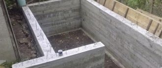
Pit and trench for ground loop
- Then it is advisable to dig a small pit of the intended shape to a depth of 1 meter. The minimum depth is 0.5 m. At the same time, a trench is dug to the same depth - a grounding bus will go along it from the contour to the base of the house.
You don’t have to dig a pit, but limit yourself to digging trenches
- The task can be somewhat simplified by digging not a solid pit, but only trenches along the perimeter of the contour being created. The main thing is that their width allows free driving of electrodes and welding work.
The edges of the corners need to be cut and sharpened so that they fit into the ground more easily.
- Electrodes of the required length are prepared. The edge with which they will be driven into the ground must be sharpened with a grinder, cutting it at an angle. The metal must be clean and unpainted.
The electrodes are sequentially driven into the ground to the required depth.
- At the designated locations, the electrodes are driven into the ground using a sledgehammer or electric hammer. They are buried so that in the pit (trench) they protrude above the surface level by about 200 mm.
Electrodes are connected by welding with a steel strip
- After all the electrodes are clogged, they are connected with a common busbar (horizontal grounding conductor) made of a 40 × 4 mm metal strip. Only welding is applicable here, although you can find recommendations to use a bolted connection. No, to ensure reliable and durable grounding, this harness must be welded - a threaded contact placed underground will quickly oxidize, and the circuit resistance will increase sharply.
The busbar is welded to the circuit and routed to the base of the building
- Now you can lay a bus from the same strip to the foundation of the house. The tire is welded into one of the clogged electrodes and placed in a trench, then it goes onto the base of the building.
- The busbar is attached to the base. Not shown in the figure, but it is advisable to provide a small bend in front of the attachment point, the so-called “compensation hump,” to compensate for the linear expansion of the metal during temperature changes. A bolt with M10 thread is welded at the end of the strip. A copper terminal with a grounding wire will be attached to it, which will go to the distribution panel.
Terminal transition to ground wire
- To pass the wire through the wall or through the base, a hole is drilled and a plastic sleeve is inserted into it. The wire used is copper, with a cross-section of 16 or 25 mm² (it is better to check this parameter with specialists in advance). It is also better to use copper nuts and washers for connections.
In this case, the grounding bus from the fittings is brought inside the room
- Sometimes they do it differently - a long steel pin is welded to the tire, so that it passes right through the wall of the house, also through the sleeve. In this case, the terminal part will be indoors and will be less susceptible to oxidation under the influence of high air humidity.
Bronze distribution plate for connecting ground wires
- The grounding wire is connected to the electrical distribution panel. For further “distribution”, it is best to use a special plate made of electrical bronze - all the grounding wires going to the points of consumption will be attached to it.
Upon completion of installation, it is necessary to check the functionality of the system.
Do not rush to immediately fill the installed circuit with soil.
— It is recommended, firstly, to capture it in a photograph with reference to surrounding stationary ground objects - this may be required to make changes to the design documentation, as well as to carry out control and verification activities in the future.
— Secondly, it is necessary to check the resistance of the resulting circuit. For these purposes, it is better to invite specialists from the energy supply organization, especially since their call, one way or another, will be necessary to obtain permits.
If the test results show that the resistance is high, it will be necessary to add one more or even more vertical electrodes. Sometimes, before checking, they resort to tricks by generously watering the areas around the corners hammered into the ground with a saturated solution of ordinary table salt. This will certainly improve the performance, however, do not forget that salt activates metal corrosion.
Ordinary table salt significantly reduces the circuit resistance, but, alas, activates metal corrosion
By the way, if it is not possible to hammer in the corners, then they resort to drilling wells to the required depth. After installing the electrodes, they are filled with clay soil as densely as possible, which is also mixed with salt.
After the functionality of the grounding loop has been checked, it is necessary to treat the welds with an anti-corrosion compound. The same can be done with the bus going to the building. Then, after the mastic has dried, the pit and trenches are filled with soil. It must be homogeneous, not littered and free of crushed stone inclusions. Then the backfill area is carefully compacted.
Video: installation of a grounding loop using a metal corner
Using ready-made factory kits
Ready-made factory-made kits are very convenient for organizing grounding at the dacha. They are a set of pins with couplings that allow you to increase the depth of immersion into the ground as you drive.
Single pin grounding system
This grounding system provides for the installation of one pin electrode, but to a greater depth, from 6 and even up to 15 meters.
The kit usually includes:
- Steel pins 1500 mm long with a galvanized or copper-plated surface, or made of stainless steel. The diameter of the pins may differ in different sets - from 14 to 18 mm.
Set of rods for assembling the grounding electrode
- To connect them, they are equipped with threaded couplings, and for ease of penetration through the ground, a steel tip is included in the kit.
Threaded coupling and ferrule for easy driving
In some kits, the couplings are press-fit rather than threaded. In this case, one end of the ground rod is tapered by forging and has a ribbed surface. When impacted, a strong connection occurs and reliable electrical contact is achieved between the rods.
The pins can also have a press-fit coupling
- To transmit the impact, a special attachment (dowel) made of high-strength steel is provided, which will not be deformed by the impact of the hammer.
Dowel - a nozzle that will transmit the impact force from the hammer
- Some kits include a special adapter that allows you to use a powerful hammer drill as a driving tool.
Hammering the electrode using a hammer drill
To install such a grounding system, it is also advisable to dig a small pit up to a meter deep and the same in diameter, although some even prefer external placement.
Growing the electrode as it is driven into the ground
The pins are driven in sequentially and incrementally to the required depth.
Then a brass contact clip is put on the area left on the surface (about 200 mm).
Either a metal bus or a ground wire can be inserted into such a contact clamp
Either a conductive busbar made of a metal strip is inserted into it, or a grounding cable with a cross-section of 25 square meters is inserted. mm. For connection to the steel strip, a special gasket is provided, which does not allow for electrochemical contact between the ground of the rod and the steel (zinc). Subsequently, the bus or cable is brought into the house and connected to the distribution panel in exactly the same way as described above.
Video: manually driving pin electrodes
Prices for components for lightning protection and grounding
Components for lightning protection and grounding
What type of rod coating should I choose – galvanized or copper-plated?
- From an economical point of view, galvanizing with a thin layer (from 5 to 30 microns) is more profitable. These pins are not afraid of mechanical damage during installation; even deep scratches left do not affect the degree of protection of the iron. However, zinc is a fairly reactive metal, and while protecting the iron, it oxidizes itself. Over time, when the entire zinc layer has reacted, the iron remains unprotected and is quickly “eaten up” by corrosion. The service life of such elements usually does not exceed 15 years. And making the zinc coating thicker costs a lot of money.
Comparative test: galvanized (left) and copper-plated (right) electrode after 10 years of operation in an aggressive acidic soil environment
- Copper, on the contrary, without reacting, protects the iron it covers, which is more active from a chemical point of view. Such electrodes can serve for a very long time without compromising efficiency; for example, the manufacturer guarantees their safety in loamy soil for up to 100 years. But during installation, care should be taken - in places where the copper plating layer is damaged, a corrosion area will likely appear. To reduce the likelihood of this, the copper plating layer is made quite thick, up to 200 microns, so such pins are much more expensive than conventional galvanized ones.
What are the general advantages of such a set of grounding systems with one deeply placed electrode:
- Installation is not particularly difficult. No extensive excavation work is required, no welding machine is needed - everything is done with ordinary tools that are found in every home.
- The system is very compact; it can be placed on a tiny “patch” or even in the basement of the house.
- If copper-plated electrodes are used, then the service life of such grounding will be several tens of years.
- Thanks to good contact with the ground, minimal electrical resistance is achieved. In addition, the efficiency of the system is practically not affected by seasonal conditions. The level of soil freezing accounts for no more than 10% of the length of the electrode, and winter temperatures cannot in any way negatively affect the conductivity.
There are, of course, some disadvantages:
- This type of grounding cannot be implemented on rocky soils - most likely, it will not be possible to drive the electrodes to the required depth.
- Perhaps some will be put off by the price of the kit. However, this is a controversial issue, since high-quality rolled metal for a conventional grounding scheme is also not cheap. If we also add the duration of operation, simplicity and speed of installation, and the absence of the need for specialized tools, then it is quite possible that this approach to solving the grounding problem may seem even more promising from an economical point of view.
Video: how to ground your home using a modular pin system
In what cases is it necessary to check the ground loop?
If you are installing a grounding device in a private house or country house, then the test can be performed with a regular test light (as described above), but if you need to put the facility into operation, legalize a change in the power supply scheme, or enter into a power supply agreement with a specialized organization , then you will need a ground loop test report.
This document can only be issued by a certified laboratory that will take measurements. In this case, the contractor that installed the grounding loop is obliged to provide you with a passport for the grounding loop with certificates for hidden work.
Features of 220 and 380 V grounding schemes
The connection in each case is special. The only thing that remains unchanged is the outer contour. The design can be any (closed, linear). But from the moment you enter the house, you need to take into account some nuances. The same applies to the wiring device. A voltage of 220 Volts requires a two-wire line. In this case, one will have to be split into “ground” and “neutral”. The other is mounted on insulators.
380V is a power supply that uses a four-wire system. One of the cores must be split, as in the previous case. The rest are mounted through insulators without contacting each other. Another feature of this installation method is the need to use additional protective equipment. These are RCDs and differential circuit breakers. A “neutral” conductor is connected to them.
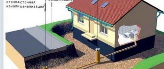
Why do you need a ground loop?
Before we deal with the question of whether grounding is necessary in a dacha area and why it is done at all, let’s first get acquainted with the basics of the theory of protective systems used in electrical networks. Let's start with the fact that most suburban buildings are connected to a network with an operating voltage of 220 Volts. It consists of two conductors, called phase and neutral, and a protective wire, used differently in different grounding systems. The two most common ways to use it are shown in the figure below.
Grounding and grounding diagram
In any of these schemes, the third core makes it possible to organize so-called “re-grounding” on the consumer side, ensuring protection of people from unexpected electric shock. This can happen completely accidentally (due to damage to the insulation, for example) and high voltage entering the body of the household appliance.
If the latter is reliably grounded (electrically connected to the ground loop), then the threat of injury is sharply reduced. This is explained by the fact that when voltage hits the protected housing, its value instantly decreases to ground potential (almost to zero). The person simply does not receive a strong current discharge and manages to leave the danger zone.
The design of all electrical appliances, power tools, as well as various types of household appliances, includes a power cord with a third grounding conductor that protects the user from high voltage.
For its reliable operation, it will be necessary to install sockets in the apartment that have the same additional contact connected to the protective circuit.
From the above it follows that installing grounding at the dacha yourself is not only a recommendation, but also a necessary measure. Particular importance is attached to this issue in suburban areas, where it is much easier to build a grounding structure than in a city apartment.
Additional information: There are objections that all of the listed problems can be solved by installing electrical protective devices such as RCDs.
However, even with these devices, reliable grounding will not be superfluous at all, since it will only complement the complex of protective measures.
Grounding of individual household appliances and equipment
It often happens that owners of private houses (especially country houses) do not see the point in installing full grounding. We cannot justify or condemn anyone, which means it is also worth considering this option. Let's figure out how to ground a water heater in a private house without installing the entire protection system.
Grounding sign GOST-21130
This is quite easy to do using a natural grounding electrode. From it you need to lay a cable directly to the device or to the outlet from which the device is powered. Often, a gas boiler in a private home is grounded in this way, but any other household appliance can be protected in this way.
There are “electricians” who, when asked how to ground an outlet in a private house, advise throwing a jumper from the neutral contact to the grounding one. It is clearly not worth listening to such advice - it is fraught with problems. We will definitely talk about such errors today. And now it’s worth taking a closer look at how to check a finished grounding loop to see if it meets the necessary requirements.
The connection seams on the tires must be well welded
Differences between traditional and pin grounding
The traditional ground loop, which is usually installed independently, is a very bulky and labor-intensive underground structure.
Several vertical electrodes (angle, pipe, rod) are hammered in, a trench is dug between them, and they are all connected to each other by horizontal connections (tire or rod).
The distance between the vertical electrodes must be no less than their length. What's wrong with this method?
Firstly, few people want to dig up their plot with meter-long trenches, and if the territory has already been improved, then a deadlock situation generally arises. In addition, all these rusty metal corners, pipes and tires, being in the ground, after a few years of operation (literally within 5-7 years) begin to rapidly deteriorate.
Therefore, today another grounding system has become very popular, namely, modular pin or deep. The most famous manufacturing companies in our area are Galmar and ZandZ.
As is known, the resistance of the grounding device depends on:
- soil type
- time of year
- electrode depths
Thus, if one electrode is driven to the maximum possible depth by gradually increasing it, then ideal resistance values can be obtained. Deep grounding works on this principle.
In addition, it:
- much more durable
- much easier to install
- and at the same time it is not so expensive (you can find kits for about 5,000 rubles)
Plus to all this, the entire installation is done without welding.
It is the need for welding that stops many people from doing this work themselves. Either there is no apparatus, or there are no necessary skills.
So you have to hire third-party electricians.
All grounding takes up space on the territory of your home, literally a few square centimeters.
And it can be done without any problems right in the basement of the building.
On average, it turns out that in a private house without a boiler, in order to achieve the required 30 Ohms, you will have to drive an electrode with a total length of 6-9 meters. For a house with gas heating (R=10 Ohm) - 9-15 meters.
These are averages. More accurate data is always individual and directly depends on the region where you live, the quality and composition of the soil.
If your house is built on sand, definitely buy a 15-meter kit. Even without a gas boiler.
The distance of the grounding route from the wall is also regulated. Unlike the input cable, it must be at least 1 meter.
For underground cable entry this figure is 0.6 m. Why so, read in detail about these and other requirements in a separate article.
Ready-made grounding kits for a private home
Self-installation can significantly reduce the cost of the grounding system. However, ready-made kits allow you to speed up work and increase the reliability of the circuit. The following models can be distinguished:
- ZandZ is a circuit with one or more stainless steel electrodes. Allowed depth is up to 10 m. The price depends on the length of the pins. The average price of a set with five-meter electrodes is 23,500 rubles.
- Galmar - has electrodes up to 30 m long. The average price is 41,000 rubles.
- Elmast . This system is manufactured in Russia and adapted to Russian operating conditions. Price – from 8000 rubles.
Important! There are many models on the Russian market, which allows you to make the best choice. The driving depth of their electrodes ranges from 5 to 40 m. The price range is 6,000-28,000 rubles.
Common mistakes when performing installation work
There are a number of characteristic shortcomings that people who are not specialists are susceptible to. If you know them, you can avoid possible mistakes. The list includes:
- Treatment of electrodes with moisture protection. Some people simply paint them, not realizing that the paint layer eliminates conductivity. Electricity is not released, the system does not perform its intended function.
- Refusal to weld. The welding machine is expensive, you don’t want to pay rent, and there is a misconception that the connection pins can be connected with bolts. Such fasteners will retain electrical conductivity for no more than one to two weeks. Corrosion will cause failure.
- Attempts to “move” the external contour as far as possible from the residential building. As a result, throughput decreases as the total resistance of the system increases. This occurs because the input is too large and becomes an obstacle to the movement of electrons.
- Saving on profile and wires. An insufficient section will work until the first case. Then the wires or other elements simply burn out, and it’s good if the grounding gets the job done until then. Next time, the harmful consequences of the short circuit are inevitable.
- Applications of copper and aluminum. Again, such a solution is resorted to in the name of economy. Often there are veins in the garage, workshop, or storage room. But when connecting such conductors, welding is impossible, which means that corrosion will eventually damage the circuit.
As soon as there is reason to think that there is a problem and the grounding is not working, find out what the problem is. Eliminate it immediately. Only in this case can the safety of property and health of family members be guaranteed. Hoping that the threat will not arise is perhaps the biggest mistake. This is why fires happen in private homes, people suffer, and household appliances break down.