Here you will learn:
- Principles of installation of water-type systems
- Installation diagram of a warm water floor on a concrete base
- Modular scheme on a wooden base
- Rack laying scheme on a wooden base
- Polystyrene scheme
- Connection diagram for underfloor heating directly from the boiler
- Installation diagram of a heated floor from a three-way valve
- Wiring diagram for a heated floor from a pumping and mixing unit
- Connection diagram for heated floor from radiator
- Features of connecting the structure to a heat source
- Water circuit installation diagrams
- Commissioning
Order the footage of floor pipes only after making calculations. Without calculating the heated floor, you cannot start purchasing materials and assembling the system; the absence of a project will negatively affect the heating of the room.
Professional calculations of the water floor are carried out by heating engineers; a rough calculation can be done independently according to the instructions:
- We determine the installation location of the distribution manifold. We measure the area of the heated rooms and determine the diameter of the pipes in the heating circuit.
- When using a pipe with a diameter of 16 mm or 20 mm, the length of the circuit does not exceed 100 and 120 m. The circuit heats 15 - 20 m2 of floor, the difference in the length of the circuits does not exceed 15 m.
- Before drawing up a scheme for laying a water heated floor, we determine the permanent location of large furniture in which we do not lay a heated floor.
- The distance between the pipes in the circuit is 15 - 20 cm, depending on the negative temperature in winter. In northern regions, at temperatures below – 30*C, this distance is reduced to 10 cm.
- Based on the area of the rooms, we calculate the number of heating circuits, determine the need for coolant and select a collector. To learn how to calculate heated floors using the program, watch this video:
Principles of installation of water-type systems
First you need to prepare the base: level it and clean it of dirt. After this, a layer of thermal insulation is laid, often using extruded polystyrene foam boards.
This material comes in the form of slabs that are not difficult to install. After this, the thermal insulation material is covered with a waterproofing film.
Before installation, a damper tape is placed around the perimeter of the room to compensate for thermal expansion during system operation. In large areas it is installed not only along the walls, but also in the seams running in the middle of the room.
If the insulation and tape are laid correctly, then the film can be carefully tucked over the edge of the insulating material, it will lie flat and with little tension.
A damper tape installed around the perimeter of the room is necessary when using a concrete screed for laying TP, in order to compensate for thermal expansion.
Hot water pipes need to be laid on top of the film, it is at this stage that the installation scheme for a water heated floor should be implemented, it is chosen in advance. The pipes should be laid evenly, trying to maintain an equal distance between them in order to achieve uniform heating of the floor.
Whatever the chosen TP scheme, you should bend the pipe correctly and carefully lay it out along the marking grid so that the floor is heated evenly
The laid communications are connected to the distribution manifold, through which they are connected to the heating system of the house, to the boiler, etc. The pipes are filled with concrete screed, after which it is necessary to wait for it to dry completely. All that remains is to check the operation of the system and lay the flooring.
Each pipe loop is connected to a manifold. It is desirable that individual sections of the system have approximately equal length and hydraulic resistance
There are no small details when installing systems of this type. A small error can cause serious damage in the future.
Therefore, it makes sense to consider a number of useful tips before starting installation work:
- It is better to completely dismantle the old screed, and place the waterproofing and insulation on the strongest possible base, carefully leveled horizontally.
- You should not think that under the screed the unevenness of the base will be invisible; all differences of more than 10 mm must be carefully leveled out.
- If several separate circuits of the system are installed in one room, the space between them should be divided with a damper tape, not limited to just laying it around the perimeter.
- In small areas, it is quite acceptable to use penofol as insulation.
- Above an unheated basement or on the ground, you need to make the most reliable insulation, for example, a layer of expanded clay and expanded polystyrene slabs at least 50 mm thick.
- When attaching pipes to the mesh, do not tighten the ties too tightly so as not to damage the pipe.
- The diameter of the pipe for such a system can vary between 16-20 mm, the material must be designed for a pressure of at least 10 bar and heating up to 95 degrees.
- If you have a limited budget, you should not spend money on pipes with options in the form of additional protection, although reinforcing polypropylene communications with fiberglass will not be superfluous.
- To automate the operation of the system, you need to correctly select and install the collector, supplementing its design with servos, pressure sensors, air vents and other useful devices.
- The collector box is placed in a niche on the wall; it must rise high enough above the floor level so that the pipes entering it can be correctly bent.
- All pipes must exit the manifold downward, and never upward, to ensure proper operation of devices for removing air trapped in the system.
- It is not recommended to make a niche for the collector in load-bearing walls; if there is no other option, it is better to simply install the cabinet on the wall, and not inside it.
For obvious reasons, it can be very difficult to correct flaws after the installation of such a system is completed, so all operations should be performed very carefully. For example, each loop must consist of one solid pipe; no soldering or any other connections are allowed.
Types of water floors and their structure
There are 4 types of water heated floors. They all have a different structure and laying pattern. Which of these is better is up to you to decide. Everywhere has its pros and cons.
Wooden floor modular type
It consists of ready-made elements - modules (22 mm chipboard) in which they were pre-milled with channels. Installation takes place on floor beams. Insulation is laid between the joists. The pitch between the beams is 600 mm. When using ceramics – 300 mm.
Installation of the modules is very simple, just lay the modules on the floor. To connect the system to each other, a special lock is used, which is already installed in the elements.
The modular and slatted type of floor is used for a wooden base (in wooden houses), which is installed on wooden logs.
Step by step instructions:
- Make sure that the wooden floor on which you plan to install the heating system is level and clean. If the floor creaks, the wood is beginning to rot, there are cracks, or there is a feeling of draft under the boards - it is better to redo the surface.
- Make the distance between the lags strictly no more than 60 cm.
- Next, nail to the beams and to the bottom - plywood or board. This will be a raised floor to hold the heated floor.
- Place insulation on top of the raised floor. But first line it with a layer of polyethylene. On top of all this is polystyrene foam or, better yet, glass wool.
- Next, lay the finished modules, fastening them together with locks.
- Insert the coolant pipe into the grooves of the modules.
- Next, you can lay the laminate. In some cases, a layer of reinforcement (aluminum plate, substrate) is laid between the laminate and the heated floor.
Wooden slatted floors
This system differs from the modular type in its design. If the module uses ready-made elements, then it is necessary to form grooves in the rack system (laying out boards 28 mm thick and with a 20 mm distance between the slats).
The rack version is also installed on logs (beams) with the same spacing as in the modular version. Insulation is placed between them.
Aluminum plates are used if the laying step is 150, 200 or 300 mm. In places where there will be heat losses (corner wall of an apartment, windows), a step of 150 mm is used.
It doesn’t matter whether you choose a modular or rack system, you should know that for each of them a separate project is drawn up with a unique calculation of the load on the heating system.
The pitch of the circuits, their number, installation of distribution manifolds and other automatic systems are taken into account.
Concrete system
This system is most often used when installing heated floors. The idea is simple - pipes are installed and filled with concrete.
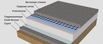
What does the scheme (filling) of a concrete system consist of:
- Thermal insulation (it is recommended to use polystyrene foam more often). Needed to keep the room warm. So that the heating does not go down to the floor, but up - into the room and its space.
- Iron mesh. Installation is carried out on thermal insulation (polystyrene floor). Pipes are attached to it with special clamps. There are many other accessories for fastening this type of floor (clips, rails, harpoons).
- Damper tape. It is laid out around the perimeter of the room even before pouring. It is a compensator for thermal expansion when the screed heats up.
- Pipes (from 8 to 32 mm). The choice of pipe diameter directly depends on the volume of the heating area and the load on the heating system. Pipe laying is carried out only according to special instructions. project. Before filling them, the entire system is tested for operability and for leaks.
- Concrete pouring (screed). This is a concrete solution. It is poured last. The final stage of installing heated floors.
Watch the video in which craftsmen install the floor and fill it with concrete screed. You will see how to correctly distribute the screed along the base of the pipes: evenly, without differences or lumps.
We pour the screed over the warm floor. Screed on beacons. Details
Installation diagram of a warm water floor on a concrete base
Scheme of a water heated floor on a concrete base
Installation of water heated floors with concrete screed
Installing water heating on a concrete base contains several “layers of the cake”.
Advantages and disadvantages of schemes
Installation diagrams for water heated floors in a private house have the following advantages compared to other heating options:
- In homes with large areas they help reduce energy costs.
- Provide uniform heating of the room.
- The device is characterized by increased safety, since there is no risk of burns or injury.
- Pipes do not spoil the interior of the room.
- Warm floors go well with many finishing materials.
- Possibility of different connection options.
Installation of heated floors in cottages is becoming increasingly popular.
The disadvantages include the large amount of time required to install the system. If leaks appear, you will have to remove most of the floor covering, including the screed.
Modular scheme on a wooden base
Provides for the use of ready-made OSB boards with sawn grooves for pipes and metal plates. The thickness of the slabs is at least 22 mm; in the diagram, the installation of thermal insulation is provided in the ceiling. The variety of modules in configuration allows them to be placed in the desired sequence according to the developed scheme. Depending on the pitch of the plastic pipe, it is possible to use strips measuring 130–280 mm. They have convenient latches for fixing pipes. Sizes 150 mm, 200 mm and 300 mm. After assembling the pipes and checking them for leaks, the circuit is covered with gypsum fiber boards.
Warm floor on a wooden base
Photo of laying heated floor pipes
General requirements for wiring diagrams
The room should be divided into sections depending on the configuration. Draw a preliminary sketch of the heating circuit on paper. In this case, two conditions must be met: the number of heating pipes in each section should be approximately the same, and sharp turns should be avoided if possible. The maximum area of one section cannot exceed ≈20 m2, the length of the pipes on it is no more than 100 m. Specific values depend on the power of the pump and the technical characteristics of the heating pipes.
Connection diagram for a water heated floor boiler
Installation diagrams can be made from plastic (the cheapest and fairly durable option), corrugated stainless steel (in all respects they occupy an average position) and copper (the most expensive and most reliable option) pipes.
Pipes for heated floors
Corrugated stainless steel pipes
Next, you need to draw a pipe layout diagram on paper, taking into account the above conditions. The distance between the pipes is 15–30 cm, depending on the required indoor temperature. It should be borne in mind that floor coverings cannot heat up more than + 30°C.
Important. When drawing a diagram, you should know that pipes have different bending radii, depending on their diameter and material of manufacture. For floor heating, the bending radius must exceed ten diameters.
When drawing up a diagram, one more condition must be fulfilled. In the room, each circuit should have the same length of pipes and approximately the same number of bends. The schemes provide for pipe laying using a spiral method, a zigzag and a snake; it is possible to use several methods in one room, it all depends on the characteristics of the floor configuration. It is recommended to increase the density of heating pipes near windows, otherwise the floor underneath them will be much colder.
Heated floor connection diagram
Pipe flow depending on pitch
The length of each circuit increases by about two meters; they will be required for connecting to the riser. If you can be a little mistaken with plastic pipes, then copper ones are too expensive to cut them into pieces; unproductive waste increases the cost of the heating system. It is possible that you will have to draw several sketches, change the appearance and size of the outline. If you have very little knowledge, and you had problems with geometry at school, then professional experts recommend taking a piece of rope or thin wire and laying out circuit diagrams on the base, changing their location, trying to make the diagram with a coil or spiral.
Pipe laying options
Methods for laying out water heated floor pipes
Having found the optimal solution, the circuit layout can be marked on the base with a felt-tip pen. Further development of the installation depends on the type of base.
Rack laying scheme on a wooden base
The diagram is drawn taking into account the use of wooden or OSB slats with a thickness of at least 28 mm. The slats should be laid on the floor joists, the distance between them is slightly larger than the diameter of the pipes. Metal profile plates are used as fasteners; there are latches on top. The system is covered with gypsum fiber boards.
Warm floors on a wooden base
Polystyrene scheme
Polystyrene underfloor heating system
A more modern method, there is no need to make a concrete screed. This scheme significantly speeds up installation work and allows the system to be used not only during new construction, but also during major renovations of the building. Due to the minimum thickness of all layers, it is possible to reduce the height loss of the room and minimize the load on the floor.
Polystyrene system
The scheme involves embedding aluminum plates into polystyrene plates in which pipes are fixed. The thickness of the slabs allows you to hide pipes with a diameter of up to 20 mm in them.
Fragments of installation of a polystyrene system
The top of the system is covered with gypsum fiber boards. It is not recommended to use plywood or OSB; they have insufficient thermal conductivity, which will reduce the efficiency of the heating system. Gypsum conducts heat well, and the addition of synthetic fibers makes it quite durable. Finish flooring can be laid on top of these slabs.
The polystyrene system can have a base thickness from 15mm to 70mm
Connection diagram for underfloor heating directly from the boiler
This connection diagram for a water heated floor has a heat generator, safety fittings with a pump. The coolant directly from the boiler enters the distribution manifold of the heated floor and then diverges through the loops and is reversed back to the boiler. The boiler must be set to the temperature of the warm floor.
This raises two nuances:
- It is advisable to use a condensing boiler for installation, because Low temperature mode is optimal for it. In this mode, the condensing boiler has maximum efficiency. In a conventional boiler, when operating at low temperatures, the heat exchanger will very quickly fail. If the boiler is solid fuel, then a buffer tank is needed to correct the temperature, since this boiler is difficult to adjust temperature.
- A good option for underfloor heating is when it is connected to a heat pump.
Prices for installation work of heated floors
Installation diagrams for water heated floors made in a private house may have different costs. It will include materials, preparatory and installation work, as well as connection and strength testing of circuits. The cost of work per square meter varies from 1,500 to 3,000 rubles. The price is also affected by the type of base and the quality of the equipment.
Installation of pipes on a wooden base
Helpful advice! It is recommended to purchase ready-made sets of equipment for underfloor heating. Many manufacturers offer a free calculation of the entire system.
Installation diagram of a heated floor from a three-way valve
Three way thermostatic valve diagram
In most cases, with such a scheme for installing and connecting a water heated floor, we have a combined heating system, there are heating radiators with a temperature of 70-80°C and a heated floor circuit with a temperature of 40°C. The question arises of how to make forty out of these eighty.
For this, a three-way thermostatic valve is used. The valve is installed on the supply side, after which a circulation pump must be installed. From the return of the heated floor, the cooled coolant is mixed with the coolant that is obtained from the boiler circuit and which is subsequently reduced to operating temperature using a three-way valve.
The disadvantage of this scheme for laying out a heated floor is that it is impossible to control the proportionality of mixing the cooled coolant with the hot one, and underheated or overheated coolant can flow into the heated floor. This reduces the comfort and efficiency of the system.
The advantage of this scheme is ease of installation and low cost of equipment.
This scheme is more suitable for heating small areas and where there are no high customer requirements for comfort and efficiency, where there is a desire to save money.
In real life, the circuit is extremely rare due to the instability of radiators connected to a single pipe. When the three-way valve is opened slightly, the heating circuit is energized, and the pump pressure is transferred to the main line.
Example implementation:
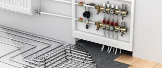
Manifold for underfloor heating system
For heated floors, a common collector unit is most often installed, or a separate collector is installed in front of each heating circuit. If the latter option is implemented, then all collectors are equipped with flow meters, thermostats, as well as the following elements:
- Return and supply mixing valve;
- Shut-off valve for balancing the heating device;
- Overflow valve.
You can assemble a collector for a heated floor yourself using different schemes, and in some schemes of collector units bypasses are used, but not always - only in single-circuit systems. If the underfloor heating system is organized according to a dual-circuit scheme, then the collector can be connected without a bypass to the secondary circuit.
Double-circuit underfloor heating system with collector
Before assembling a manifold assembly for a heated floor, weigh your options - sometimes it’s easier to buy a ready-made structure. If you are going to buy a collector, it is better that all its parts and elements are from the same manufacturer. When assembling the unit yourself, you must select the material from which the main components of the unit will be assembled: copper, steel, polymers or brass.
Also, when choosing an industrial design, it is important to consider the following parameters:
- How many heating circuits will there be in the system (usually from 2 to 12), the total length of the pipeline and the capacity of the circuits;
- Maximum permissible pressure in pipes;
- Possibility of expanding the heating system;
- Manual or automatic collector control;
- Electrical power of all components and assemblies;
- The diameter of the internal holes of the collector (throughput).
Do-it-yourself collector
The most efficient operation of the assembled collector units can be ensured by connecting heating circuits of equal length to them. In order to equalize the length of the pipelines with sufficient accuracy, they are divided into equal sections, which are connected to the collector. The easiest way is to calculate the collector unit in a special computer program or on an online calculator, so that the phenomenon called “thermal zebra” does not appear, that is, uneven heating of the floor.
For the calculation you will need the following data:
- Type of decorative flooring;
- the area of the heated room and the plan for placing large objects in it;
- Material and diameter of circuit pipes;
- Boiler rated power;
- Type of floor insulation.
Reservoir calculation
Collector installation - recommendations
When designing a heated floor system, you first need to find the optimal location for installing the collector. Typically, the unit is installed in a manifold cabinet, and the cabinet itself is mounted at a height of 30-40 cm from the floor level next to the supply and return.
In order not to blame your own mistakes and ensure maximum heating of the heated floor pipes, study the instructions for connecting the collector. Then assemble the unit in the following sequence (this applies to an industrial manifold unit):
- Unpack the tubes for forward and reverse coolant supply. The tubes must have flow meters and supply valves. If the collector is multi-sectional, assemble the sections into one structure;
- From the assembled sections you need to assemble a unit on brackets (included in the kit);
- Next, we install shut-off valves, automation, sensors and other connecting fittings;
- We attach the unit to the wall or in a cabinet, install a thermostat, a servo drive and a circulation pump;
- We connect the pipes from the boiler and the pipes from the heating circuits of the “warm floor” system.
Manifold set
Now the connection diagram for the heated floor collector is pressed, after which the concrete screed can be poured. Thermal adjustments of the collector can be carried out after installation of the finishing coating.
DIY collector unit
A factory manifold is a fairly expensive product, so many craftsmen want to make it themselves. You will still have to buy many elements, but the cost will be cheaper. The easiest way is to solder a homemade manifold from PVC pipes and fittings Ø 25-32 mm. You will also need tees and bends of the same diameters, and shut-off valves.
Homemade collector
The number of valves and fittings is calculated by the number of heating circuits. The tools you need are a soldering iron for propylene elements and attachments for it, special scissors for cutting pipes and a tape measure.
Marking the collector consists of marking and cutting pipes of the required length, observing the minimum distance between the tees. Valves and transitions are soldered to the PVC tees with a soldering iron. Fittings for connecting the pump are soldered to this structure. As you can see, everything is simple, but it is better to buy more complex collector units ready-made.
Wiring diagram for a heated floor from a pumping and mixing unit
Mixing module
This is a mixed scheme for connecting a water heated floor, where there is a radiator heating zone, a heated floor and a pumping and mixing unit is used. The cooled coolant is mixed from the heated floor return to the boiler.
All mixing units have a balancing valve, with which you can dose the amount of cooled coolant when mixing it with the hot one. This allows you to achieve a clearly defined temperature of the coolant at the outlet of the unit, i.e. at the entrance to the heated floor loops. This significantly increases consumer comfort and efficiency of the system as a whole.
Depending on the model of the unit, it may include other useful elements: a bypass with a bypass valve, a balancing valve of the primary boiler circuit, or ball valves on both sides of the circulation pump.
Connection diagram for heated floor from radiator
These are special kits designed to connect one underfloor heating loop to an area of 15-20 sq.m. They look like a plastic box, inside of which, depending on the manufacturer and configuration, there may be coolant temperature limiters, room air temperature limiters and an air vent.
The coolant enters the loop of the connected water heated floor directly from the high-temperature circuit, i.e. with a temperature of 70-80°C, cools down in the loop to a given value and a new batch of hot coolant enters. An additional pump is not required here; the boiler must cope.
The disadvantage is low comfort. Overheated zones will be present.
The advantage of this scheme for connecting a water heated floor is that it is easy to install. Such kits are used when there is a small area of heated floors, a small room with infrequent occupants. Not recommended for installation in bedrooms. Suitable for heating bathrooms, corridors, loggias, etc.
Let's summarize and put it in a table:
| Connection type | Comfort | Efficiency | Installation and configuration | Reliability | Price |
| Regular gas, TT or diesel | ± | ± | + | ± | + |
| Condensing boiler or heat pump | + | + | + | ± | — |
| Three way thermostatic valve | ± | ± | + | + | ± |
| Pumping and mixing unit | + | + | ± | + | — |
| Thermal mounting kit | — | ± | + | + | + |
Master plumbers and heat and gas supply experts recommend avoiding schemes for connecting water heated floors to working heating branches. It is better to power the heating circuits of the underfloor heating directly to the boiler so that the floor heating can function independently of the radiators, especially in the summer.
Features of connecting the structure to a heat source
In a floor circuit, most often the average coolant temperature is 35-40 degrees. Installation diagrams for water heated floors in a private house operate using forced mixing of flows. Part of the coolant from the return flow passes into the supply circuit.
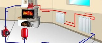
Thermostat connection diagram
Gas boilers are equipped with special automation. Solid fuel units require a more complex device. They are equipped with circulation pumps and a special buffer tank. In this case, more complex combustion adjustment is used.
Location of the boiler in a separate room
Electric boilers are considered the best option for underfloor heating systems. Special automation allows you to maintain the desired temperature without loss of thermal power.
Electric boiler in operation
Helpful information! To heat small houses, a direct connection to an electric boiler is used. In cottages with a large area, a special distribution comb is used.
Nuances of installation
The technology of installation diagrams for water heated floors in a private house is determined by the characteristics of a particular heating circuit.
Construction installation options are influenced by many parameters
The installation work of the structure has the following distinctive features:
- The base for the equipment is selected taking into account the floor covering.
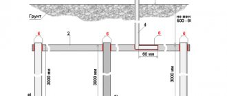
1 – floor beam; 2 – longitudinal beam; 3 – logs; 4 – mortgages for pipes; 5 – pipe; 6 – finishing coat
- A damper tape is installed around the perimeter of the room. The shock-absorbing element reduces heat loss at the junction of the floor and wall surfaces.
Features of laying damper tape
- The system itself is mounted on concrete slabs in a screed.
Screed installation for water heated floors
- Waterproofing, reinforcing mesh and a layer of insulation are laid on the base.
Laying waterproofing material on the base
- Pipes are mounted to the frame using clamps or steel wire.
Installation to a frame structure
For heated floors, special seamless pipes are used. The circuit is mounted from a solid line. The pipe material must be resistant to corrosion and resistant to high temperatures.
Special pipes for the water circuit
Helpful information! Profile mats made of extruded polystyrene foam can be used as a frame and insulation. Then the canvases are covered with a layer of waterproofing.
Water circuit installation diagrams
If the installation of warm water floors is carried out using a well-established, traditional technology in a clear sequence, then the installation of a heating pipe can be carried out in various variations. The main goal pursued when installing heated floors is to uniformly heat the entire area of the heated room. Laying a pipeline just the way you want means deliberately creating problem areas throughout the entire structure. The coolant tends to quickly lose temperature as it flows, so the pipes must be laid starting from the walls, then moving towards the entrance to the room or to its center. For this purpose, specially developed optimal schemes for laying the water circuit, each of which has its own characteristics.
The mixing unit and manifold are the beginning of the entire heating system. Water circuits are connected in a clear sequence. The beginning of the pipeline is to the inlet pipe, the end of the pipe is connected to the check valve.
You can install a warm water floor with your own hands, the contour of which will be laid as follows:
- pipe installation according to the snake pattern"
- laying the pipeline according to the snail pattern;
- combined scheme.
When installing heating in corner rooms, a pipe laying scheme is used for enhanced heating.
In each individual case, we can talk about the advantages of one or another scheme. For example: a snail is the simplest circuit. The bend of the pipe here reaches 900, while in a snake the heating pipe will be bent by 1800.
Note: the “snake” type water circuit can be powered by a low-power circulation pump. For a bathroom or children's room, this installation scheme looks preferable.
Where heated rooms have a linear slope, it is better to install the pipe according to the “snake” pattern. The pipeline is laid in the direction from the mixing unit towards the slope. Air pockets in this version can be easily removed, which cannot be said about a pipe laid in a snail pattern. In sloping rooms, removing air pockets can be problematic.
For large premises where it is necessary to use several water circuits of the same length for heating, the “snake” pipeline laying scheme is very convenient. Thanks to this installation method, it is possible to achieve balanced operation of the entire heating system.
Heating pipes laid on a prepared base are connected to a manifold that distributes the supply of coolant to the system. The distribution cabinet together with the mixing unit is installed either in the heated room or next to it, which significantly reduces the number of pipes and the consumption of other materials. The bends of the water pipe at the point of connection to the collector are sewn into a special protective box.
In each individual case, a certain order of laying the water pipe should be followed. When working with a snail circuit, the pipe is first laid along the perimeter of the walls, after which a turn follows from the farthest wall. In the opposite direction, the pipe is laid in a spiral, reaching the center of the heated room. For the snake circuit, the water circuit is laid out as follows. The pipe is laid along the perimeter of the walls, after which uniform bends are made in the opposite direction.
The combined installation schemes of heating pipes for heated floors, used in some cases, involve the simultaneous use of both options. One half of the room can be heated by a water circuit laid in a snake pattern, while the other part of the room will be heated by a pipe mounted in a snail pattern.
How to draw up a floor laying plan according to plan?
The diagram is created even before you have purchased all the materials. It helps not only to correctly install a heated floor, but also to plan the volume of purchasing materials.
To begin, draw a picture of the room in which you plan to install it. This could be 1 room, the whole apartment or the whole house (private). Make the drawing correctly, in accordance with the size of your room. A diagram “by eye” will not give any accuracy. Take into account the square meters of the room and transfer it to paper or the workspace of the software on your PC.
In this video you can familiarize yourself with a PC program for designing a heated floor plan. Video review, presentation of the program's capabilities, brief instructions on how to use it.
Warm floor program
What is included in plan accounting:
- building plan (including all floors);
- material of floors, walls, windows and doors;
- desired temperature in the heated room;
- location of collectors and heating boiler;
- detailed arrangement of furniture, its dimensions taking into account the square footage. meters of premises;
- average ambient temperature in winter;
- the presence of another heat source (battery, fireplace, split system, etc.)
Tips and tricks at the stage of creating a diagram:
- The approximate area for 1 circuit should be more than 15 square meters. m.
- In large rooms, install multiple circuits. They should not differ in length by more than 15 m.
- If the step is 15 cm, it will be equal to the pipe flow rate of 6.7 m per 1 sq. m. If the installation is every 10 cm, then the consumption will mean per 1 sq. m – 10 meters.
- The minimum pipe bend radius is 5 times its diameter.
- Considering that heated water will first pass through the pipes, and then it will gradually cool and return to the collector already cooled, installation should begin in those places that are most susceptible to cooling (windows, corner walls).
- The circuit plan can be drawn manually on graph paper.
In the video, the master manually draws a diagram for installing a heated floor on paper. Gives clear examples of calculations.
WARM FLOOR PROJECT, CALCULATION, PUMP (for a large room)
It is important to save the finished wiring diagram (drawn or printed). In emergency cases (leakage, sale of an apartment, repair work), precise knowledge of the location of the pipes may be necessary.
When drawing up a diagram, keep in mind that the collector is installed in the center of the room (see diagram below). It is important that the distance of all contours is approximately the same.
Which installation option is better? Preference should be given to the scheme that best suits a particular room. This has already been discussed above.
Scheme for a two-story house
The plan below shows a diagram of laying heated floors on 2 floors. The first floor has a large area, so the “Snail” double-circuit heating system is used.
Multi-room premises (house, apartment)
The plan shows that “Snail” is used throughout the room. This applies to both the bathroom and kitchen. Please note that the contours do not go under furniture, appliances or plumbing fixtures.
Scheme for a room with complex curved walls
When laying the floor, you may encounter some difficulties - curved walls, unique, designer layouts. In such cases, it is not easy to install an even snake or snail. A combined laying system is used.
The coolant is laid based on the shape and bend of the walls. Look at the picture below to see how you can plan your pipe laying scheme. The interior space is also taken into account when warming up.
Commissioning
Full maturation of the cement screed occurs after a month, which is when balancing needs to be done using collector flow meters.
Using balancing valves, the coolant flow is regulated; it should become the same in all circuits. If you have no experience with self-balancing, it is better to invite a specialist.
After manipulating with cold water, if the system is working correctly, you can conduct tests with heated coolant. At this point, the installation of the heated floor is considered complete.