Until recently, electrical wiring in a private house was made of aluminum cable with a cross-section of 2.5 mm². And this was more than enough to connect a refrigerator, iron or radio.
However, time does not cost less, and every day the number of household appliances in the house only increases (air conditioners, electric stoves and ovens, boilers, autonomous heating boilers, and so on). In this regard, the load on the electrical wiring increases significantly, which can lead to its failure, followed by a short circuit or even a fire.
For this reason, during new construction or renovation work, it is first necessary to carry out new installation of electrical wiring in a private house. To do this, you can either order the services of professionals, or do all the work yourself.
In the second case, it will be extremely useful to read this article, since it will describe in detail each of the stages of electrical installation and present all the basic requirements, recommendations and limitations when performing this type of work.
The main stages of installing electrical wiring in a private or country house
According to many years of experience in performing electrical installation work, all work can be divided into the following stages:
- Drawing up a power supply diagram (number and location of sockets, switches, lamps, etc.).
- Determining the installation location of the distribution panel.
- Marking ceilings, walls and floors for laying cables and wiring products and installing socket boxes and distribution boxes.
- Chasing walls for hidden electrical wiring.
- Grooving walls for installing a distribution panel (when installing an internal panel).
- Drilling holes for installing socket boxes and distribution boxes.
- Installation of routes for fastening the corrugation (if the laying of cable and wire products will be carried out in the corrugation).
- Laying of cable and wire products.
- Installation of socket boxes and rough sealing of grooves.
- Disconnection of distribution boxes.
- Installation of the ground loop.
- Checking the grounding resistance of the mounted circuit.
- Assembly and installation of the shield.
- Checking the functionality of all sockets and switches.
- Installation and connection of sockets, switches and lighting fixtures.
Let us consider in more detail the main stages so that the installation of electrical wiring in the house is carried out with high quality and will last at least 20–25 years (this is exactly the minimum service life of copper wiring).
Electrical equipment, light, lighting
80 votes
+
Vote for!
—
Vote against!
Just 15–20 years ago, the load on the power grid was relatively small, but today the presence of a large number of household appliances has provoked an increase in loads significantly. Old wires are not always able to withstand heavy loads and over time there is a need to replace them. Laying electrical wiring in a house or apartment is a task that requires certain knowledge and skills from the master. First of all, this concerns knowledge of electrical wiring rules, the ability to read and create wiring diagrams, as well as electrical installation skills. Of course, you can do the wiring yourself, but to do this you must adhere to the rules and recommendations outlined below.
- Electrical wiring rules
- Electrical wiring design and diagram
- Electrical wiring installation
- Marking and preparing channels for electrical wiring
- Installation of open electrical wiring
- Installation of hidden electrical wiring
Electrical wiring rules
All construction activities and building materials are strictly regulated by a set of rules and requirements - SNiP and GOST. As for the installation of electrical wiring and everything related to electricity, you should pay attention to the Electrical Installation Rules (abbreviated PUE). This document describes what and how to do when working with electrical equipment. And if we want to lay electrical wiring, then we will need to study it, especially the part that relates to installation and selection of electrical equipment. Below are the basic rules that should be followed when installing electrical wiring in a house or apartment:
- key electrical wiring elements such as distribution boxes, meters, sockets and switches must be easily accessible;
- Switches are installed at a height of 60–150 cm from the floor. The switches themselves are located in places where an open door does not prevent access to them. This means that if the door opens to the right, the switch is on the left side and vice versa. The wire to the switches is laid from top to bottom;
- It is recommended to install sockets at a height of 50–80 cm from the floor. This approach is dictated by flood safety. Also, sockets are installed at a distance of more than 50 cm from gas and electric stoves, as well as heating radiators, pipes and other grounded objects. The wire to the sockets is laid from bottom to top;
- the number of sockets in the room must correspond to 1 pc. for 6 m2. The kitchen is an exception. It is equipped with as many sockets as necessary to connect household appliances. Installation of sockets in the toilet is prohibited. For sockets in the bathroom, a separate transformer is installed outside;
- wiring inside or outside the walls is carried out only vertically or horizontally, and the installation location is displayed on the wiring plan;
- wires are laid at a certain distance from pipes, ceilings, etc. For horizontal ones, a distance of 5–10 cm from the floor beams and cornices and 15 cm from the ceiling is required. The height from the floor is 15 - 20 cm. Vertical wires are placed at a distance of more than 10 cm from the edge of the door or window opening. The distance from gas pipes must be at least 40 cm;
- when laying external or hidden wiring, it is necessary to ensure that it does not come into contact with metal parts of building structures;
- when laying several parallel wires, the distance between them must be at least 3 mm or each wire must be hidden in a protective box or corrugation;
- The wiring and connection of wires is carried out inside special distribution boxes. The connection points are carefully isolated. Connecting copper and aluminum wires to each other is strictly prohibited;
- grounding and neutral wires are secured to the devices with a bolted connection.
Electrical wiring design and diagram
Electrical wiring work begins with the creation of a project and wiring diagram. This document is the basis for future wiring of the house. Creating a project and diagram is quite a serious matter and it is better to entrust it to experienced specialists. The reason is simple - the safety of those living in a house or apartment depends on it. Project creation services will cost a certain amount, but it's worth it.
Those who are accustomed to doing everything with their own hands will have to, adhering to the rules described above, and also having studied the basics of electrical engineering, independently make a drawing and calculate the load on the network. There are no particular difficulties in this, especially if there is at least some understanding of what electric current is and what the consequences of careless handling are. The first thing you need is some symbols. They are shown in the photo below:
Using them, we make a drawing of the apartment and mark lighting points, installation locations for switches and sockets. How many and where they are installed is described above in the rules. The main task of such a diagram is to indicate the location of installation of devices and routing of wires. When creating an electrical wiring diagram, it is important to think in advance where, how much and what kind of household appliances will be installed.
The next step in creating the diagram will be to route the wires to the connection points on the diagram. It is necessary to dwell on this point in more detail. The reason is the type of wiring and connection. There are several such types: parallel, sequential and mixed. The latter is the most attractive due to the economical use of materials and maximum efficiency. To facilitate wiring, all connection points are divided into several groups:
- lighting of the kitchen, corridor and living rooms;
- toilet and bathroom lighting;
- power supply for sockets in living rooms and corridors;
- power supply for kitchen outlets;
- power supply socket for electric stove.
The above example is just one of many options for lighting groups. The main thing to understand is that if you group the connection points, the amount of materials used is reduced and the circuit itself is simplified.
Important! To simplify wiring to sockets, the wires can be laid under the floor. Wires for overhead lighting are laid inside the floor slabs. These two methods are good to use if you don’t want to scratch the walls. In the diagram, such wiring is marked with a dotted line.
The electrical wiring project also indicates the calculation of the expected current in the network and the materials used. The calculation is performed using the formula:
I=P/U;
where P is the total power of all devices used (Watt), U is the network voltage (Volts).
For example, a 2 kW kettle, 10 60 W light bulbs, a 1 kW microwave, a 400 W refrigerator. Current strength is 220 Volts. As a result (2000+(10x60)+1000+400)/220=16.5 Amperes.
In practice, the current strength in the network for modern apartments rarely exceeds 25 A. Based on this, all materials are selected. First of all, this concerns the cross-section of electrical wiring. To make your choice easier, the table below shows the main parameters of the wire and cable:
The table shows extremely accurate values, and since the current strength can fluctuate quite often, a small margin will be required for the wire or cable itself. Therefore, it is recommended that all wiring in an apartment or house be made from the following materials:
- wire VVG-5*6 (five cores and cross-section 6 mm2) is used in houses with three-phase power supply to connect the lighting panel to the main panel;
- wire VVG-2*6 (two cores and cross-section 6 mm2) is used in houses with two-phase power supply to connect the lighting panel to the main panel;
- wire VVG-3*2.5 (three cores and cross-section 2.5 mm2) is used for most of the wiring from the lighting panel to the distribution boxes and from them to the sockets;
- wire VVG-3*1.5 (three cores and cross-section 1.5 mm2) is used for wiring from distribution boxes to lighting points and switches;
- wire VVG-3*4 (three cores and cross-section 4 mm2) is used for electric stoves.
To find out the exact length of the wire, you will have to run around the house a little with a tape measure, and add another 3 - 4 meters of reserve to the result obtained. All wires are connected to the lighting panel, which is installed at the entrance. Circuit breakers are installed in the panel. Typically these are 16 A and 20 A RCDs. The former are used for lighting and switches, the latter for sockets. For an electric stove, a separate 32 A RCD is installed, but if the power of the stove exceeds 7 kW, then a 63 A RCD is installed.
Now you need to calculate how many sockets and distribution boxes you need. Everything is quite simple here. Just look at the diagram and make a simple calculation. In addition to the materials described above, you will need various consumables, such as electrical tape and PPE caps for connecting wires, as well as pipes, cable ducts or boxes for electrical wiring, and socket boxes.
Electrical wiring installation
There is nothing overly complicated about electrical wiring installation work. The main thing during installation is to adhere to safety regulations and follow the instructions. All work can be done alone. Tools for installation will require a tester, a hammer drill or grinder, a drill or screwdriver, wire cutters, pliers, and a Phillips and slotted screwdriver. A laser level will not be superfluous. Since without it it is quite difficult to make vertical and horizontal markings.
Important! When carrying out repairs and replacing wiring in an old house or apartment with hidden wiring, you must first find and, if necessary, remove the old wires. For these purposes, an electrical wiring sensor is used.
Marking and preparing channels for electrical wiring
We begin installation with markings. To do this, use a marker or pencil to place a mark on the wall where the wire will be laid. At the same time, we follow the rules for placing wires. The next step will be to mark the locations for the installation of lighting fixtures, sockets and switches, and the lighting panel.
Important! In new houses, a special niche is provided for the lighting panel. In the old ones, such a shield is simply hung on the wall.
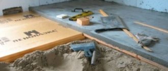
Having finished with the markings, we proceed either to install the wiring in an open way, or to groove the walls for hidden wiring. First, using a hammer drill and a special bit, holes are cut for installing sockets, switches and distribution boxes. For the wires themselves, grooves are made using a grinder or a hammer drill. In any case, there will be a lot of dust and dirt. The depth of the groove of the groove should be about 20 mm, and the width should be such that all the wires fit into the groove without obstruction.
As for the ceiling, there are several options for solving the issue of placing and securing the wiring. The first is that if the ceiling is suspended or suspended, then all the wiring is simply fixed to the ceiling. The second is to make a shallow groove for wiring. Third, the wiring is hidden in the ceiling. The first two options are extremely simple to implement. But for the third one you will have to make some explanations. In panel houses, floors with internal voids are used; it is enough to make two holes and stretch the wires inside the floor.
Having finished with the gating, we move on to the last stage of preparation for wiring installation. Wires must be pulled through the walls to bring them into the room. Therefore, you will have to use a hammer drill to punch holes. Usually such holes are made in the corner of the room. We also make a hole for running the wire from the distribution panel to the lighting panel. Having finished gating the walls, we begin installation.
Installation of open electrical wiring
We begin the installation by installing the lighting panel. If a special niche was created for it, then we place it there; if not, then we simply hang it on the wall. We install an RCD inside the shield. Their number depends on the number of lighting groups. The assembled and ready-to-connect panel looks like this: there are neutral terminals at the top, grounding terminals at the bottom, and automatic circuit breakers are installed between the terminals.
Now we insert wire VVG-5*6 or VVG-2*6 inside. On the switchboard side, the electrical wiring is connected by an electrician, so for now we will leave it unconnected. Inside the lighting panel, the input wire is connected as follows: we connect the blue wire to zero, the white wire to the top contact of the RCD, and the yellow wire with a green stripe to ground. We connect the RCD circuit breakers to each other in series at the top using a jumper from the white wire. Now we move on to open wiring.
Along the previously outlined lines we fix boxes or cable channels for electrical wiring. Often, with open wiring, they try to place the cable channels themselves near the baseboard or vice versa, almost under the ceiling. We secure the wiring box using self-tapping screws in increments of 50 cm. We make the first and last hole in the box at a distance of 5 - 10 cm from the edge. To do this, we drill holes in the wall using a hammer drill, drive a dowel inside and secure the cable channel with self-tapping screws.
Another distinctive feature of open wiring are sockets, switches and distribution boxes. All of them are hung on the wall, instead of being built inside. Therefore, the next step is to install them in place. All you have to do is place them on the wall, mark the mounting locations, drill the holes and secure them in place.
Next we proceed to wiring the wires. We start by laying the main line and from the sockets to the lighting panel. As already noted, we use wire VVG-3*2.5 for this. For convenience, we start from the connection point towards the panel. At the end of the wire we hang a label indicating what kind of wire it is and where it comes from. Next, we lay the VVG-3*1.5 wires from switches and lighting fixtures to the distribution boxes.
Inside the distribution boxes, we connect the wires using PPE or carefully insulate them. Inside the lighting panel, the main wire VVG-3*2.5 is connected as follows: brown or red wire - phase, connected to the bottom of the RCD, blue - zero, connected to the zero bus at the top, yellow with a green stripe - grounding to the bus at the bottom. Using a tester, we “ring” all the wires to eliminate possible errors. If everything is in order, we call an electrician and connect to the distribution panel.
Installation of hidden electrical wiring
Concealed electrical wiring is quite simple. The only significant difference from the open one is the way the wires are hidden from view. Otherwise the actions are almost the same. First, we install the lighting panel and RCD circuit breakers, after which we start and connect the input cable from the side of the distribution panel. We also leave it unconnected. An electrician will do this. Next, we install distribution boxes and socket boxes inside the made niches.
Now let's move on to wiring. First we lay the main line from VVG-3*2.5 wire. If it was planned, then we lay the wires to the sockets in the floor. To do this, we insert the VVG-3*2.5 wire into a pipe for electrical wiring or a special corrugation and lay it to the point where the wire exits to the sockets. There we place the wire inside the groove and insert it into the socket box. The next step will be to lay the VVG-3*1.5 wire from the switches and lighting points to the junction boxes, where they are connected to the main wire. We isolate all connections with PPE or electrical tape.
At the end, we “call” the entire network using a tester for possible errors and connect it to the lighting panel. The connection method is similar to that described for open wiring. Upon completion, we seal the grooves with gypsum putty and invite an electrician to connect it to the distribution panel.
Installing electrical wiring in a house or apartment is quite easy for an experienced technician. But for those who are not well versed in electrical engineering, they should take the help of experienced professionals from start to finish. This, of course, will cost money, but this way you can protect yourself from mistakes that could lead to a fire.
Drawing up a power supply diagram (project for the placement of sockets and switches)
During construction or major repairs, the first stage is the development of design and estimate documentation. This should be done by specialized organizations with a license. This option will not be considered in this article, since the purpose of this article is to provide a detailed description of doing electrical installation yourself.
In our case, the project (electrical supply diagram) involves determining the installation locations of sockets, switches, household appliances, lighting devices, lighting panels and the method of laying wires (hidden or open). Let's consider what basic recommendations exist when developing a power supply plan.
Basic recommendations when drawing up a power supply diagram for a private home
- All cable and wire products, regardless of installation option, must be made strictly vertically or horizontally.
- Rotations of cables must be made strictly at an angle of 90°.
- The minimum distance from cables to portals, window and door openings should not be less than 10–15 cm.
- The optimal distance from the finished floor level to the switches should be 90 cm (in accordance with European standards).
- The optimal height for the location of socket groups is 30 cm from the level of the finished floor (with the exception of sockets on the work surface in the kitchen, in the bathroom for connecting a hair dryer, razor, boiler, etc.).
- It is recommended to place sockets on both sides of the bed or sofa.
- In places where TVs are installed, the number of sockets must be at least 4 pcs (2 pcs for the Internet and television cable and 2 for connecting a TV and tuner).
- For large corridors and rooms, it is recommended to use pass-through switches.
- All powerful consumers (air conditioners, electric stoves and ovens, boilers, heating boilers, etc.) must be connected exclusively from a distribution panel with separately installed protection.
- The optimal installation height for the distribution panel is 1.5–1.7 m from the finished floor level.
- It is prohibited to lay cables and wires closer than 20 cm to the gas pipe.
- All metal elements and sockets must be grounded.
What is the usual wiring diagram in a private home?
Of course, houses can be very different from each other, but the essence of high-quality installation is approximately the same for everyone, and it is as follows:
- An electric meter is installed on the facade of the building, to which a descent is made from the overhead line via a self-supporting insulated wire (the electricity supply organization is responsible for this part and for the meter).
- A voltage stabilizer(s) and a power distribution panel or automation are installed in a garage or some other room, which controls and transmits electricity through an input copper cable with a cross-section of 10–35 mm².
- A generator is installed on the street near the room where the switchboard is located, which supplies the house in the absence of a centralized power supply.
- On each floor inside the house there is a separate distribution panel, to which the input cable is connected in parallel.
- The distribution panel contains separate RCDs for the sockets of each room, circuit breakers separately for each room and separate RCDs for air conditioners, boilers, heating boilers and underfloor heating systems.
- All powerful consumers are powered strictly from the distribution panel, which provides for the installation of individual protection elements (RCD).
- A separate distribution box must be installed in each room, in which the input cables and cabling and wiring products of the socket group and lighting circuits will then be switched.
Important! When drawing up a power supply plan, it is necessary to take into account the type of supply network. If you have a 3-phase network, then the input cable to the house should have 5 mils; in the case of single-phase power supply, the number of cores of the supply cable should be 3.
Once you have decided on the power supply circuit and installation locations for electrical accessories, you can begin marking out the room.
How to plan wiring
In order for the process of laying wiring to be carried out very competently and at the same time the wiring to serve for a long time, it is necessary to carry out proper planning for its implementation. In other words, you need to make a diagram.
Experts recommend deciding on a list of sockets, lamps, as well as all possible mechanisms and devices that require individual connection.
This list must be compiled for each room and each auxiliary building. When developing this list, it is worth considering that in the future the list of electrical appliances will only expand.
Taking this into account, you need to decide where and how additional devices will be connected.
In the process of planning the placement of outlets, it is also worth deciding on the location of electrical appliances and other electrical “users” that will be used in the future.
That is, you need to decide where the chandeliers will be placed, where the TV will be, and where the refrigerator and other devices will be placed.
It will not be superfluous to determine the connection points for those electrical installations that will be used outside the house, that is, in the yard or landscaped area.
When this work is done, we begin to draw up a wiring diagram that will be used in a private house. Drawing up such a diagram is very important. Thanks to it, it will be possible to determine all the required quantities of materials.
At the same time, during installation you will not forget to install some kind of socket or run a certain cable. Another advantage of this arrangement is that in the future, when making repairs, you will know where all the electrical wires run.
This will eliminate any possibility of accidental damage to the cable during repair work.
What should the wiring be like?
It is worth noting that drawing up a diagram has its secrets. These secrets concern the correct routing of cables and their wiring. Let's note how to do the wiring correctly.
So, electricity enters a private house through an electric meter. After it, a distribution board is installed. It is from this shield that the wiring of various wires begins. Each of them can be called a circuit.
The number of these circuits directly depends on the number of rooms in a private house and electrical devices that are planned to be used. A small private house may have only two circuits.
One of them is assigned for sockets, the other for lighting fixtures.
Helpful advice: when drawing up any wiring diagram, regardless of the size of a private house, there should always be a separate wiring for lighting and a separate wiring for sockets.
The reason for this is that lighting fixtures and appliances plugged into outlets have different wattages. As a result, powering light fixtures requires thinner wires than powering a refrigerator, microwave, or any other electrical device.
In fact, this advice can be called mandatory. This will save on the purchase of cables. Otherwise, that is, if you connect both sockets and lamps to the same wiring, then if the cable burns out or shorts, you will not be able to use any device or lamp that is connected to this wire.
It should be borne in mind that it is better to organize a wiring diagram that will provide for the wiring of more circuits than a private house requires. This will reduce stress on the wires and eliminate the need for additional wiring in the future.
A mandatory rule is to equip each circuit with a circuit breaker. The group of circuits must also be connected to a differential relay (RCD). Both the switch and the RCD are mounted in the distribution panel.
When drawing up a diagram, you need to take into account one more nuance: there are electrical appliances that have more power (water pump or electric stove). For them you need to use a cable with a large cross-section. Of course, this cable will be a separate circuit.
If a private house consists of several floors, then electricity must be supplied to each floor through a separate wiring. Experts recommend connecting rooms separately.
Where to install switches
It is worth paying attention to the fact that the requirements for electrical wiring in some rooms are more stringent. The list of these rooms includes those that are characterized by the constant presence of water and high levels of humidity. An example is a bathroom, toilet or laundry room.
The main requirement for these rooms is to move all switches outside of them. That is, switches cannot be installed in the middle of them. Compliance with this requirement will increase the level of safety.
As for other rooms, you can use switches in them. It is advisable that they be at a height of 90-140 centimeters. In this case, the distance between the wooden door frame and the switch should be 15 centimeters.
The switch should be on the same side of the door as the handle. The circuit must also include a grounding circuit.
Once you have made the wiring diagram, you can begin installing each wire and all electrical accessories. One of the main processes is wiring installation. It can be carried out in various ways.
Marking the room
In order to mark the room you will need:
- ordinary building level;
- water or laser level;
- construction pencil;
- beating thread;
- roulette.
Initially, using a laser level (water level) and a tape measure, we mark the installation locations of sockets and switches. Next, using a building level or a laser level and a pencil (mark), we mark the descents from the ceiling to the sockets and switches using strictly horizontal lines for subsequent cutting.
Using a laser level, we mark on the ceiling the places where cable and conductor products will be laid for the subsequent installation of fasteners for corrugations and cable laying.
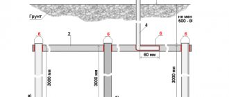
We mark the installation location of the distribution box, which should be selected in such a way that the costs of cable and wire products are minimal.
Important! When marking the ceiling, keep in mind that all cables from sockets and switches and input cables to socket groups and lighting circuits will be brought into the distribution box, therefore, when installing corrugated fasteners, it is necessary to calculate how many cables will go where.
Wall chipping
After completing the markings, when performing hidden electrical installations, you can begin to groove the walls. To do this, you will need either an angle grinder (grinder) or a wall chaser with a vacuum cleaner (for dust-free chasing):
Initially, it is necessary to determine the depth of the groove. Let's say you are installing a cable in a corrugated cable with a diameter of 16 mm. In this case, the depth and width of the groove must be at least 20 mm. The grooves are cut according to pre-made markings.
Important! It is prohibited to make grooves at an angle or to groove load-bearing structures (crossbars, load-bearing walls, floor slabs, etc.).
Also, at the stage of wall slitting, it is necessary to make a hole for installing an internal distribution panel. Its dimensions depend on the number of modules. In most cases, a distribution panel with 24–36 modules should be installed on each floor (depending on the number of rooms and the number of household appliances).
Drilling holes for electrical outlets and distribution boxes
For this we need:
- Hammer;
- Crown for socket boxes d68;
- Crown for distribution boxes d100.
To drill holes, turn on the “drilling + drilling” mode, insert the required crown and drill the required number of holes in the pre-marked places.
Important! When installing several sockets nearby, you need to buy junction boxes, attach them to the installation site and only then drill holes. Because otherwise you will not be able to install sockets with covers that are installed under one strip.
Installation of cable and wire products
In most cases, with high-quality installation, all cable and wire products are laid in corrugation. This provides additional protection for the cable, simplifies installation and makes subsequent replacement possible if the cable fails without opening the walls and disrupting the repairs performed. It is also worth noting that do-it-yourself electrical wiring in a house is done in 90% of cases in a hidden way (in grooves) and very rarely in cable ducts in an open way.
What type of cable and wire products to choose
Here, of course, you need to perform a lot of calculations, but based on many years of experience, I would like to note:
- To power the lighting circuits, a 3x1.5 mm² cable (PVSng, VVGng ShVVPng) is required.
- To power the socket group of each room, a 3x2.5 mm² cable.
- To power household air conditioners, the cable is 3x2.5 mm², but if its power is more than 5 kW, then the cable cross-section must be increased to 4 mm².
- To power an electric stove and oven, the cable cross-section must be at least 4 mm².
- To power heating boilers (electric), depending on the type of power supply (single-phase or three-phase), the cable must be from 4 mm2 to 35 mm2 (depending on power). In most cases, the manufacturer writes the recommended cross-section and number of cable cores.
Important! When laying cable and wire products, each socket group must be connected from a separate RCD (precisely an RCD in accordance with the requirements of SNiP). Also from individual machines the following must be connected:
- electric floor heating systems;
- boilers;
- washing machines;
- electric stationary heaters;
- heating boilers;
- air conditioners;
- dishwashers.
What should the input cable be like?
The input cable from the meter to the house must be calculated according to the rating of the input machine (installed after the meter). But in most cases, an input cable with a cross-section of 10–16 mm2 is sufficient for a 3-phase network and 16–70 mm2 for a 1-phase supply network.
Breakdown of consumers into groups
Before you do the electrical wiring yourself, you will need to work out the issue of dividing the consumers in the house into separate groups. Its timely and correct solution will help achieve the following goals:
- Reducing the load on linear bends used to connect individual rooms in a country house.
- Convenient control of loads (their prompt switching on and off) using a separate linear machine.
- Possibility of organizing a multi-level line protection system using several RCDs with different leakage currents.
Groups of electricity consumers in a private house
Please note: According to the same PUE, powerful consumers of electricity are connected to an individual linear machine, that is, they are classified as a separate group.
Such special loads in the electrical wiring design are traditionally indicated:
- Warm floor.
- Powerful air conditioners.
- Ovens and electric stoves.
- Washing machines and other household consumers with a power of up to 10 kilowatts.
In addition, sockets installed in rooms with high air humidity (in bathrooms, in particular, or in basements and attics) are included in a separate group. Outlet products in several adjacent living rooms can also be combined into a separate group. The same rule applies to all lighting fixtures installed in a private home (chandeliers, sconces, lighting elements, etc.), which are usually divided into two or three subgroups.
Installation and wiring of the distribution box
After installing the cable and wire products, you can install distribution boxes in pre-cut holes. To securely fix them, it is necessary to use alabaster, which sets very quickly, after which you can disconnect it.
Disconnection is performed in 3 ways:
- Soldering.
- Welding.
- Terminal connection (WAGO clamps).
Important! It is better to make connections in the distribution box using color markings of the cables (blue to blue, brown to brown, yellow-green to yellow-green). This will prevent the phase from being confused with earth or grounding. In this case, the brown (white) wire is the phase, the blue (black) is the neutral, and the yellow-green is the ground.
Installation and assembly of the distribution panel
After laying cables and wires, installing and connecting distribution boxes, you can begin installing the electrical distribution panel.
How many modules should the shield be installed on?
Electrical wiring in a private house involves installing a panel on each floor in private houses, cottages or dachas. However, in order to find out how many modules are needed, you first need to calculate how many consumers there will be. Let's make a calculation for the standard version, that using its example we were able to install electrical wiring in the house with our own hands.
Let's say on your floor:
- 3 rooms.
- Kitchen;
- Corridor;
- Boiler;
- Washing machine;
- Warm floor system in 3 rooms and kitchen;
- Electric stove;
- 4 air conditioners.
Based on this, you need to install in the distribution board:
- 5 single-pole circuit breakers 10 A (lighting 3 rooms, kitchen and corridor);
- 14 pieces of RCD for 16 A (3 pieces of sockets in rooms, 1 piece of kitchen sockets, 1 piece of corridor sockets, 1 piece of boiler socket, 1 piece of washing machine socket, 3 pieces of floor heating system, 4 pieces of air conditioning);
- 1 RCD 25–32 A for connecting an electric stove.
From the above calculations, we will have 35 occupied modules (30 modules occupy 15 RCDs and 5 circuit breaker modules). That is, we will need a distribution board with 36 modules. However, if you also want to connect a voltage limiter or the number of consumers will be larger, then the shield must be mounted on 48 modules.
After installing the distribution board, you can install RCDs and circuit breakers. They are easily mounted on a special DIN rail, which comes as standard with the switchboard.
Important! When disconnecting the distribution board, the phase (brown) wires must go through automatic machines or RCDs, the neutral (blue) wires must be collected on the zero bus, and the yellow-green wires must also be connected on the 2nd zero bus).
Selection of cables and components
Today's standard wiring diagram for a private house includes two circuit breakers. One - input - is installed before the meter, usually on the street. It and the meter are sealed upon commissioning. The second RCD machine is placed in the house in front of the panel.
The operation (shutdown) current of these devices is selected so that the circuit breaker installed in the house is turned off first (its current value is slightly less). Then, in the event of an emergency, you will not need to crawl under the roof.
If the design load is less than 15 kW, the input circuit breaker is set to 25 A. The meter is selected accordingly. For higher power consumption, it will be necessary to install a transformer; its parameters and the parameters of all equipment will be indicated in the project.
Recently, when connecting a private house to the power grid, they are required to install a meter and a machine on the street. This requirement is not supported by law; it is simply easier for the electricity service to control consumption.
If you want, you can fight, if not, choose a meter and machine in a case with increased dust and moisture resistance - a protection class of at least IP-55. For installation inside a building, the protection must be less - IP-44, and accordingly the price will be lower.
Which wire to use for wiring in the house
And so, to install electrical wiring, the owner of a private house needs to stock up on a certain amount of cable and electrical accessories (we will consider its types below). The cable can be copper or aluminum. Of course it must have insulation.
It is better to use copper cable. The reason for this is that it has more bandwidth. This makes it possible to use wire with a smaller cross-section.
Another advantage of a copper cable is that it can withstand a greater load than an electrical wire made of aluminum.
It’s also worth saying about this moment. A private house can be supplied with both single-phase and three-phase power. In the case when it is necessary to supply current to single-phase devices, the cable must be three-core.
One conductor is phase, the other is neutral, and the third is intended for grounding. In case of laying three-phase power, the cable must be five-core.
For wiring, both flat (convenient to install under plaster) and round cables can be used. Their important characteristic is the cross section.
The choice of electrical wire with a certain cross-section depends on the load level. So, if a wire is laid to the sockets, then this value should be at least 2.5 square meters. millimeters. Cables for powering lighting devices must have a cross-section that is at least 1.5 square meters. millimeters.
In order not to make a mistake with the cross-section of the electrical wire, you need to calculate the power of all possible devices that will be powered from a separate wire. Of course, you need to take into account some amount as a reserve.
After this, the total power must be divided into 220 (if one phase enters the house) or 380 volts (if there is a three-phase network). As a result, you will know the current that the cable must carry.
Based on this value, you can determine the desired cross-section. To do this, you need to use special tables.
Necessary electrical accessories and requirements for them
- As for the electrical accessories that will be used in a private home to create electricity. wiring, then it can consist of:
- mounting boxes;
- sockets;
- any types of switches;
- switches;
- call buttons and other types.
Mounting boxes are used in any room and can be characterized by different shapes. So, their shape can be round, square or rectangular. The purpose of these boxes may vary.
Some of them are used to install sockets or switches. They are mounted under the plaster and do not have a top cover. There are also boxes that are also installed under the plaster, but have a lid. They are either distributional or through.
In addition to these, there are also external (outer) boxes. It is worth noting that most boxes are not sealed. However, some are sealed.
Helpful Hint: Various wires are often connected and routed in these boxes. To connect them you need to use a distribution ring and special clamps. If you simply twist the wires and use insulating tape, then such a connection will be unreliable. The result is sparking in the box. And that's the minimum.
As for sockets, now you need to use sockets with three poles. The third pole is a safety contact that connects to the ground wire.
It is also worth mentioning the fact that it is recommended to use double sockets. They will make it possible to reduce the number of doubles or tees.
Both sockets and switches may or may not be sealed. It is advisable to use sealed electrical accessories on the external walls of a private house, on a balcony, porch, etc.
So, you should stock up on materials before you begin installing wiring inside and outside a private house.
If we talk about the principle of laying electrical wiring in a private house, then it is not much different from the same process within the walls of an apartment.
The main difference is that a private house can have several floors and, in addition to many household appliances, it can also use powerful electrical appliances that are part of heating, water supply systems or are intended for certain industrial purposes.
Another difference is receiving current from different sources. A private house receives current from a local transformer or from a power pole.