DIY sliding gates: step-by-step guide and diagrams
Published: February 02, 2018
Do-it-yourself sliding gates: where should you start, how to choose components, what order of actions to follow, what should you pay attention to first? This article will be useful to all those who are interested in the question of how to make sliding gates with their own hands, and also contains drawing diagrams and instructions for installation work. Below is a diagram of sliding gates, a diagram of the foundation of sliding gates, recommendations for preparing the opening, and installation recommendations.
Sliding gates are a very popular and most convenient type of gate. The name is due to the design features - they roll away from the sides and move along the fence. Over the past ten years, sliding gates have become incredibly popular. This popularity was facilitated by the development of a new, improved design - the gates became more affordable in price, got rid of the top guide and no longer require maintenance.
This article describes the most logical and optimal procedure for producing and installing sliding gates with your own hands; in addition, it contains drawing structures for a welder.
In order to independently make a sliding gate frame and install it, in addition to one desire, you must have a welding machine (inverter), as well as have welding skills. In addition, you will need a tool for cleaning seams and cutting metal. You will need a site with a relatively flat surface in order to organize some kind of slipway for assembling the gate leaf.
We will divide the work into five parts: measuring, working with the foundation, manufacturing the frame, installing the structure and finishing the canvas, installing the drive and related devices. Before starting work, it is necessary to clearly understand how exactly sliding gates work.
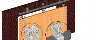
Let's look at a diagram of a sliding gate, on which all the main components are drawn:
The door leaf is made of profile pipes and is approximately 1.5 times wider in length than the opening. It can be conditionally divided into two structural parts: the main one, which obscures the opening and is subsequently subject to finishing (for example, corrugated sheets, wood) and the cantilever part, the need for which is determined by the design features. A guide 3 is welded to the lower edge of the door frame, with the slot downwards. Thanks to it, the sliding gate moves along the roller carriages 5, which are located inside. Conscientious craftsmen and prudent owners always use adjusting stands 4 to attach carriages. They make it possible to adjust the structure in two planes. Covering the opening, the sliding gates are hinged by the end roller 2 onto the lower trap 1. They are held by the upper corner by the upper roller trap 8, relieving the wind load. For this, you also need a bracket with rollers to prevent lateral rolling 7. The guide is protected from snow and fallen leaves by a special plug 6
Stage one. Do-it-yourself measurement and design of sliding (sliding) gates
To correctly calculate the length of the structure, you need to measure the initial data. The gate leaf can be made for the existing opening or can be designed simultaneously with the fence. Let's assume that the fence is already installed and we have an opening that needs to be closed. The opening is limited by pillars.
To design a gate you need the following dimensions:
- opening width
- estimated height of the installed structure - from the level of the finished road surface
- the direction of rollback of the canvas and the length of the rollback space.
The canvas can roll to the left or right of the opening. The direction of movement is determined when viewed from the yard. To roll back, you need free space along the fence = width x1.5. As a rule, the height of the gate is approximately 10-15 cm lower than the fence. The post of the opening, behind which the gate leaf rolls back, must be at least 5 cm higher than the gate to install a bracket against lateral swings 7. The gate leaf, when moving away, “hides” behind the fence. The total height of the gate is the height of the door leaf with the guide + the height of the gap under the gate.
The height of the clearance depends on the level of the mounting plate (channel) and on the height of the roller supports that are used in the structure. If the mounting plate is installed at the same level with the road surface, and the sliding gates are assembled on the ROLTEK Micro, ROLTEK ECO or DACHA system, then the clearance will be from 8 to 10 centimeters. For winters in central Russia, this gap is optimal.
If you are just designing a future fence, below are some tips that will help you save money and simplify subsequent installation.
With an opening width of up to 5 meters, you can significantly save on components, since they are divided not only by the possible weight of the structure, but also by the width of the possible opening to be closed.
A gate built into the door leaf has many disadvantages: it reduces the rigidity of the structure, cannot be equipped with an electromechanical lock, has a high (about 20 cm) threshold and is dangerous. If there is such a possibility, it would be wiser to make the gate stand-alone. It is much safer and more convenient to use.
For an opening limited by pillars of stone or brick, it is necessary to provide in advance embedded parts for installing upper and lower traps, and a roller bracket from wind loads. The embed is a metal plate with reinforcement welded perpendicularly. The reinforcement holds the embedded part in the concrete.
Stage two. Making the base - foundation
There are several options for preparing the base for sliding gates with your own hands.
Traditional and most expensive
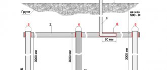
To the side to roll back the gate, parallel to the fence on the side of the yard, you need to dig a trench. Its length is 1/2 the width of the opening (for example, with an opening of 4 meters, the length of the pit = 2 meters), the width of the trench is approximately 50 cm (if you can make it narrower, this will not affect the quality, and you will save concrete), and the depth = 1 ,7m. To avoid “sliding gate distortion,” the depth of the trench is made lower than the soil freezing level.
A mounting plate is placed in the hole parallel to the fence. It is made from a channel 12-16 mm wide and half the width of the opening. The reinforcement grid will hold the channel in the concrete; it is knitted from reinforcement with a diameter of 12-16 mm. In order to save money, you can replace the fittings with unnecessary scraps of metal (angle, square or professional pipe)
The mounting plate, with the reinforcement facing down, is placed in the pit. The conventional “zero” for the gate design is the upper plane of the mounting plate. Its position determines what the minimum gap under the gate leaf will be. We recommend laying the mounting plate at the same level as the road surface - then you will get a minimum gap of 8 cm. The mounting plate should be laid as close as possible to the fence post.
Particular attention should be paid to the parallelism of the longitudinal axis of the slab channel and the opening line. The path of movement of the gate will run along the center of the channel. The channel must be laid strictly horizontally.
Pillar foundation
The support-column foundation for the gate consists of two reinforced concrete pillars, the body of which is located in the ground. The pillars are connected to each other by a mounting plate, which serves as a base for the roller trolleys. Using a garden drill, two holes are made with a depth of 1.7 -2 m and a diameter of 20 to 35 cm. The distance between the piles should be 20-30 cm less than the width of the opening. Holes for the piles must be drilled close to the fence. The pits are reinforced and embedded in them (a metal plate with reinforcement welded down). The structure is concreted. The level of the upper platform of the mortgage must coincide with the level of the road surface. When the concrete gains initial strength, you can weld the mounting plate and begin installing the canvas. The axis of the mounting plate should follow the path of movement of the future gate leaf. The plane of the slab must be positioned horizontally.
Foundation on screw piles
The practice of installing gates on screw piles in Russia is new and there have been no reviews of long-term use of gates installed this way. Customers who have had gates installed on stilts speak positively about them.
The big advantage of such a foundation is its low price and the ability to complete the work in one day, but to screw in a pile you either need to put in serious effort and skill, or use expensive equipment.
Preparing electrical wiring for installation of automation
For gates that will be opened automatically in the future, electrical wiring must be laid at the stage of laying the foundation.
Laying wiring in the ground and foundation must be done in steel or HDPE pipes. The pipes used must be intact in length. Before laying the pipe, you need to pass the wire inside it, so that later you can easily pull the wires through. The diameter of the pipe inside must be at least 30 mm. The geometry of the pipes, seams and bends should not interfere with the free passage of wiring. The depth of pipe laying depends on the soil at the installation site. The recommended type of cable for wiring is PVS flexible copper cable.
You can lay the cable in HDPE pipes with an internal diameter of 15 - 25 mm. In this case, the cable should be laid in the HDPE pipe in advance. To avoid water ingress, the electrical wire outlets must be securely sealed. An armored cable can be used.
Manufacturing of gate leaves
The first thing to establish is the width of the future opening, because... the size of the valves should be ½ of this width. For example, if the opening width is 3 m, then the size of each individual leaf will be 1.5 m. In addition, it is important to remember that there should be a gap of 1 cm between the leaves.
The manufacture of gate leaves involves the following work:
- The frame is made:
- 1) a pipe with a cross-section of 60x30 mm is cut into pieces using a grinder: you should get 4 elements measuring 2 m each and 4 elements measuring 1.5 m each;
- 2) a marking is made on the ground for one door with dimensions of 1.5x2 m, bricks are installed at the corners of this marking;
- 3) pipes from which the frame will be made are laid on the bricks according to the dimensions;
- 4) then, using available materials, the surface is leveled so that it is completely horizontal: any pieces of building material are placed under the bricks).
- The joints of the frame are welded using a continuous seam.
- After welding the joints on one side, the frame is turned over and welding is performed on the reverse side.
- Next, the frame is strengthened:
- 1) take a 20x30 profile pipe;
- 2) applied to the base frame and the elements for reinforcement are measured;
- 3) the measurements taken are transferred to the pipe, and the required elements are cut out of it;
- 4) the cut out elements are welded to the frame.
- The frame is processed: grinding welds, removing rust and metal stains.
Stage three. Manufacturing of gate leaves
To make sliding gates with your own hands, in addition to rolled metal and tools, you will need to purchase a set of fittings for the structure. In the sliding gate diagram above we described the components of the system. Fittings for sliding gates vary in the maximum width of the opening and the weight of the gate that the beam and trolleys can carry.
For example, if the gate weighs up to 350 kg, and the length of the opening is 4 meters, you can use MICRO 6, Dacha 6 components. As a rule, they are intended for private use: a cottage, a summer cottage. Weight restrictions imply light finishing from a profile sheet, mesh or picket fence.
For structures up to 500 kg and an opening length of a maximum of 5 meters, you need to use the ECO 7 kit. These can be light forged gates, structures finished with corrugated board or light wood (pine).
If the canvas weighs about 800 kg, and the opening is wide (up to 7 meters), it is necessary to select components that can cope with this task, for example, the EURO kit from the ROLTEK company.
The most powerful parts for the configuration - the MAX system - are capable of supporting a canvas weighing up to two tons, with an opening of up to 12 meters.
When purchasing components for making sliding gates with your own hands, we recommend that you consider their delivery, since the guide can be 5 or more meters long. You can transport it yourself, in the trunk of a car, or you can hire a specialist. transport, or order delivery from us. If you want the components to be delivered to another city, we will organize everything. The cost of delivery throughout Russia is not high, because the cargo is transported as a group. You can check the price of transportation by calling us.
You can cut the guide beam into 2 parts - then the delivery issue will be much easier. We perform the cut with a special cutter and the beam fits together perfectly. The guide can be welded on site without loss of quality.
To assemble a sliding gate frame for a 4*2 m opening you will need:
- profile pipe with a cross-section of 60*40 (you can also use a pipe 60*30) - 3 pipes of standard length 6 m.
- profile pipe 40*20 or 20*20 for the manufacture of sheathing (the filling of the gate leaf made of corrugated sheets, wood, etc. is attached to it) - 5 pipes of standard length 6 m.
Correct leaf design is the basis for long-lasting gate operation. The gate leaf must be rigid, but not overloaded with elements. The frame is a load-bearing truss containing the necessary diagonal and vertical load-bearing elements.
Most often, the frame is made using the technology of all-welded structures. Subsequently, it can be finished with wood, picket fence, etc.
Advantages and disadvantages
When deciding how to make a gate, it is important to take into account all the features of different designs, which will allow you to choose the most suitable option. The main criteria are the availability of free space on the site, ease of use, and the degree of complexity of installation. The swing system has its advantages:
- simple installation;
- long-term operation;
- minimal care;
- reliability;
- various design options, the ability to use any material for the manufacture of sashes;
- There is no need to specially strengthen the base; with the sliding option, in this case rollers are used and the soil will have to be poured with concrete.
You can complicate things a little by connecting a drive to them. This simplifies their operation, but complicates the installation process and increases costs. There is a need to allocate more space to install a swing structure. You are the owner of a small plot or it is already occupied (with a garden, vegetable garden or other buildings), and there is a sidewalk on the street side, you will have to install a sliding option due to lack of space.
Sliding gate drawing
Our company has been producing self-supporting sliding gates since 1992. During this time, significant changes occurred in the design. Below we will describe the most optimal, in our opinion, frame design.
Drawing of the frame of a sliding self-supporting gate for an opening 4,000 mm wide, 2,000 mm high on the ROLTEK MICRO supporting system
Drawing of nodes A, B
Material Specification:
BLANKET FOR STANDARD FRAME 4000x2000 on MICRO/ECO supporting system
| № | ANGLES | PROFILE | LENGTH | QTY | |
| 1 | 90˚/90˚ | MICRO 6 / ECO 6 | 6,000 mm. | 1 PC. | |
| 2 | 90˚/45˚ | 60x40 | 6,000 mm. | 1 PC. | |
| 3 | 45˚/45˚ | 60x40 | 4,480 mm. | 1 PC. | |
| 4 | 90˚/45˚ | 60x40 | 1,804 mm. | 1 PC. | |
| 5 | 45˚/45˚ | 60x40 | 1,844 mm. | 1 PC. | |
| 6 | 40˚/50˚ | 60x40 | 2,359 mm. | 1 PC. | |
| 7 | 45˚/45˚ | 40x20 | 4,399 mm. | 2 pcs. | |
| 8 | 45˚/45˚ | 40x20 | 1,763 mm. | 2 pcs. | |
| 9 | 90˚/90˚ | 20x20 | 1,683 mm. | 5 pieces. | |
| 10 | 90˚/90˚ | 20x20 | 703 mm. | 6 pcs. | |
| 11 | 50˚/40˚ | 20x20 | 1,089 mm. | 6 pcs. | |
For manufacturing, we recommend using a profile pipe with a cross section of 60*40 for the outer frame, 40*20 along the internal contour and 20*20 for the sheathing. It is preferable to use a thin-walled pipe - this will reduce the weight of the gate and help save on the supporting system, and subsequently on the drive.
The frame must be assembled on a welding table or on a flat surface that is larger than the structure being assembled. Welding of pipes and guides must be done with an intermittent seam in a checkerboard pattern. You cannot weld the guide completely on one side, and then turn the frame over on the other. This will cause it to bend. Before welding, the guide and pipe must be primed to avoid rust stains as a result of unpainted paint. If the geometry of the canvas is damaged as a result of assembly, it must be straightened.
Welding seams must be cleaned with a grinding machine.
Assembling the mechanical part of the gate
The next stage is the installation of guide columns, which are best purchased ready-made, since these supports will bear the entire power load. After all, even the slightest inaccuracy in their manufacture can lead to the inoperability of the entire mechanism.
The video below shows the step-by-step process of assembling sliding gates.
Next, roller catchers are mounted on the supports.
After the structure is assembled, the gate is installed on roller supports and the final adjustment of all mechanisms is made.
Remember! The movement of the gate must be smooth, strictly along a horizontal plane, without bending in the direction of movement and without wedging.
Interesting: Polycarbonate fence between neighbors in the country
Stage four. Installation of the structure and finishing of the canvas
Before installing a sliding gate, make sure that the opening is sized to fit the gate and that there is enough space for the sliding gate and that there are no obstructions.
Attention! Gates can only be installed after the foundation has completely hardened.
Sequence of actions for installing self-supporting sliding gates:
1. Place the adjusting supports on the mounting plate (channel). The distance L between the centers of the supports should be approximately 35-40% of the opening width.
For ROLTEK components it can be calculated using the formula
For sliding gates, the opening is four meters long and weighs up to 350 kg. (on the ROLTEK MICRO 6, DACHA 6 system) or with a weight of up to 500 ROLTEK ECO 6, the calculation of distances is given below
Note: an end roller is mounted in front of the sash; its installation requires space. If the roller trolley is placed close to the opening, then in the “open” position the sash will not completely clear the opening.
Using adjusting stands will allow you to correct possible installation errors without damaging the roller carriages. Sliding gates mounted on stands can be adjusted horizontally and vertically. If the foundation moves during use, the gate will be easy to level.
The adjustment stands must be secured by welding. Roller carriages are put on them, the door leaf is rolled up and final adjustments are made to the height and trajectory of movement.
Further:
- remove the gate from the roller carriages
- unscrew the roller carriages from the stands
- We scald the stand along the contour, attaching it to the mortgage, screw the roller carriages onto the stands
- roll up the canvas so that the gate is closed. Using a level and a wrench, we adjust the final position of the gate. Important! Horizontal adjustments must be made in the closed state. As a result of the adjustments made, the blade should move without effort.
- From the rollback side in front of the gate, install the end roller and tighten the fastening bolts
- Install a channel on the receiving post to attach the lower and upper traps. The channel (120 mm wide) is welded to the embedded parts. Instead, you can use a 60*40 mm profile pipe or a special reinforced bracket (ROLTEC accessories)
Attention! Traps need to be installed after the canvas is completely ready (loaded). Otherwise, their position will need to be adjusted after finishing the gate.
- Weld the upper and lower traps onto the channel, determining their position when the gate leaf arrives in place. The lower trap must be adjusted so that when closing, the sash hits it with the end roller and rises 10 mm.
- Weld the upper stop of the sash to the post behind which the leaf rolls. Adjust the position of the door leaf and the gap between the gate leaf and the rollers against lateral swings. Tighten the rollers.
Seal the gate leaf guide with a plug.
The sheathing of a fabric of this design can be made of any material up to 20 mm thick. Consider the option of finishing with a profile sheet. Corrugated sheeting of the required length can be ordered at the factory so that it fits well into the frame; its length should be taken 2 mm less than the internal dimensions of the frame. The sheets are sequentially inserted into the frame and fastened with metal screws or rivets. If the last sheet does not fit, it is cut to width.
Tools and material
To make a gate you will need the following materials:
- cladding for sashes (corrugated sheeting, wood, Euro picket fence);
- self-tapping screws;
- metal pipes with a cross section of 60x40 mm;
- loops;
- paint for painting metal products and brushes.
For the gate manufacturing process itself, you will also need tools such as:
Note!
Do-it-yourself porch to the house - the best projects and construction ideas (125 photos of new products)
DIY brick barbecue: diagrams, drawings, photos, dimensions. Review of simple and complex structures on a summer cottage!
House with a bay window - 150 photos of the best planning and design ideas. Overview of all features of an architectural element
- plumb line;
- level;
- electric drill;
- Bulgarian;
- welding machine and protective mask;
- roulette;
- metal scissors.
Stage five. Installation of electric drive and rack
Once the sliding gate is completely installed, you can begin installing the automation. The operating principle of any electric drive for sliding gates is to transfer force from the gear to the rack on the gate leaf. The slats are sold in 1 meter pieces; the amount of slats required for the gate is calculated based on the width of the opening + 1 meter. The rail can be steel - it is attached by welding to the frame - and nylon with a steel core - it can be attached to roofing screws to a ready-made gate.
Still have questions? Do you want to buy components and make sliding gates yourself? Call or come to us. We will competently answer your questions and help you with advice!
Installation and installation of swing gates with driving in metal posts
This installation method has several main advantages, we list them below:
- economically, installation is very profitable;
- installation speed increases several times;
- the possibility of replacement or repair arises;
- self-installation.
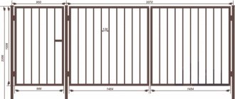
Step-by-step instructions for installing swing gates
Metal poles must be driven into the ground to a depth of about 1.5 meters.
Drive a post into a pre-prepared hole to a certain depth, being guided strictly by the level. Next, we connect the metal posts to the outbuildings or to the rest of the fence. In this case, the pillars are connected to each other by a removable strip. It is necessary to weld the frames of two sashes to the ready-made exposed supports.
Swing gates are made on a flat, smooth surface; a welding table is best to ensure that the entire structure is level and meets your expectations.