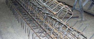
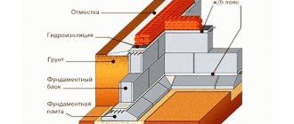
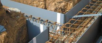
An example of strip foundation reinforcement There are a huge number of different types of foundations depending on the material and design, but they all have a key drawback - poor reliability with significant or small ground movements. Concrete is considered a durable material, but it is not able to withstand soil displacements for a long time; it slowly collapses, and with it the foundation itself.
To prevent this from happening, a special reinforced frame is used, which is mounted inside the foundation before it is poured. Reinforcement has greater tensile and tensile strength than concrete, and therefore can withstand significant loads. The design of the reinforcing belt differs significantly depending on the type of base, so it is worth considering in detail the structure of the frame for the strip base, which is popular among private developers.
Reinforcement of a monolithic foundation: 7 pressing issues
Making a reinforced concrete foundation for the construction of a private house seems quite simple. But, as practice shows, at this stage, inexperienced (or unscrupulous) builders quite often make serious mistakes, which are almost impossible to correct later. If you don’t go into the issues of proper design, there are still a lot of problems: the water-cement ratio is chosen incorrectly, too low a reinforcement density is used, there is no vibration of the laid mixture, the requirements for stripping time are ignored, operations to protect and care for the concrete during the maturation period are not carried out...
In this publication we will try to “work on mistakes” regarding the reinforcement of a monolithic foundation. The article will help the novice builder not to lose sight of the main pitfalls, and the customer will help monitor very important hidden work.
Monolithic foundation slab
Reinforcement of a monolithic slab
Why reinforce a concrete foundation at all?
Perhaps the question may seem trivial to some, but still the temptation to save on metal sometimes gets the better of the future homeowner. The results of such a decision are always disastrous.
Any foundation is a loaded structure. The mass of the entire building presses on it from above. But, oddly enough, certain forces also act on the monolith from below. This is the so-called “frost heaving”, which in winter, when the soil freezes and expands, seems to “push” the foundation to the surface. The lighter the building, and the more heaving the soil, the more susceptible the foundation is to being pushed out (which is why it is not recommended to leave foundations unbuilt over the winter).
The load on the foundation structure is multidirectional and uneven due to the presence of openings in the walls, due to the asymmetry of the structures, due to the complex composition of the soil under the structure... For example, the most vulnerable are the outer corners and T-shaped joints in the foundation system. Therefore, in addition to simple compression (which cement stone tolerates perfectly), the monolith is subjected to more complex influences: stretching, bending, torsion, and so on. And here hardened concrete, which does not have the necessary plasticity, can break. The problem of destruction here is not even immediate, but rather “fatigue,” which accumulates over time.
Steel, unlike stone, resists stretching and bending well. An elastic reinforcement rod placed inside the concrete gives the reinforced concrete product the missing properties. By adhering to concrete along its entire length, the reinforcement cage redistributes the load. Metal and stone actually complement each other.
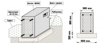
Sectional diagram of foundation reinforcement
The role of the reinforced frame
Concrete is a very strong and durable material, ideal for constructing such an important element of a building as the foundation. But there is also a small gap in its excellent track record - concrete cannot withstand large static, and even more so dynamic bending loads. To correct such a deficiency, a reinforcement frame is implanted into his body, which takes on the role of a kind of skeleton.
The metal structure in the foundation not only improves the bending performance of the concrete foundation, but also helps it to withstand all deformations and distribute any loads.
Today's careless builders lose their attention to these undeniable advantages of a metal frame, and, chasing the maximum cost reduction of construction, use a reinforced structure either partially or from low-quality metal, which subsequently causes cracks in the foundation and walls.
To prevent this from happening, purchase only high-quality metal. A diagram of the correct tying of reinforcement for a strip foundation should become the main instruction for the duration of the work on constructing the foundation.
What material should be used to reinforce the foundation?
Not so long ago, composite reinforcement began to be used when creating monoliths. However, for a number of reasons, a steel rod made of hot-rolled steel with an elastic modulus of about 200 kPa, made in accordance with GOST 10884-94 (Steel for reinforced concrete structures), remains a popular classic.
Reinforcement for strengthening the foundation can be either smooth or corrugated. The latter, thanks to its “variable cross-section,” adheres much better to cement stone, and therefore is used as the main rods. And smooth rods are most often used to form the necessary spatial configuration of the frame.
That is, the reinforcement in a monolith is usually divided into:
- Working (performs basic power functions).
- Mounting or distribution (serves to assemble the frame, redistributes the load between all working rods).
To form the working threads of the reinforcing frame, class A2 material with screw-type ribs is usually used, or A3 material with longitudinal ribs and sickle-type or ring-type notches extending from them. But class A1 reinforcement (according to GOST 5781) is just smooth rolled products, which are presented in the form of a rod or coil, if the diameter does not exceed 12 mm.
The reinforcement section is selected depending on the predicted loads, the configuration of the foundation and the selected reinforcement scheme. Obviously, it is advisable to perform engineering calculations, but approximate figures can be announced. So for a small one-story wooden frame house, the foundation is reinforced with rods with a diameter of 10-12 mm, but a stone building with large dimensions will require the use of reinforcing threads with a diameter of at least 14-16 mm.
To assemble the frame (as mounting reinforcement), smooth material of class A1 with a diameter of 6 mm, occasionally 8 mm, is most often used. By the way, nothing prevents the use of higher-class corrugated reinforcement for these purposes; it is also produced in small sections.
Types of corrugated fittings
Minimum standard diameters of reinforcement
| Location and operating conditions | Minimum size | Regulatory document | |
| Longitudinal reinforcement, no more than 3 m long | Ø 10 mm | Appendix No. 1 to the design manual “Reinforcement of elements of monolithic reinforced concrete buildings”, M. 2007 | |
| Longitudinal reinforcement, length more than 3 m | Ø 12 mm | Appendix No. 1 to the design manual “Reinforcement of elements of monolithic reinforced concrete buildings”, M. 2007 | |
| Structural reinforcement in beams and slabs over 700 mm high | Sectional area not less than 0.1% of the cross-sectional area of concrete | “Guide to the design of concrete and reinforced concrete structures made of heavy concrete (without prestressing)”, M., Stroyizdat, 1978 | |
| Transverse reinforcement (clamps) in knitted frames of eccentrically compressed elements | Not less than 0.25 of the largest diameter of the longitudinal reinforcement and not less than 6 mm | “Concrete and reinforced concrete structures without prestressing reinforcement” SP 52-101-2003 | |
| Transverse reinforcement (clamps) in knitted frames of bending elements | Ø 6 mm | “Concrete and reinforced concrete structures without prestressing reinforcement” SP 52-101-2003 | |
| Transverse reinforcement (clamps) in knitted frames of bending elements at height | less than 0.8 m | Ø 6 mm | “Guide to the design of concrete and reinforced concrete structures made of heavy concrete (without prestressing)”, M., Stroyizdat, 1978 |
| more than 0.8 m | Ø 8 mm | ||
What is the optimal reinforcement density?
Backfill density (or reinforcement density) is one of the main characteristics of reinforced concrete products in general and monolithic foundations in particular. It is estimated as a percentage of the area of the longitudinal working threads of the reinforcement to the area of the concrete. Mounting transverse elements are not taken into account here.
According to SP 52–101–2003 (Manual for the design of concrete and reinforced concrete structures made of heavy concrete without prestressing reinforcement), the total cross-section of all working reinforcement rods must be at least one tenth of a percent of the cross-sectional area of the foundation. The maximum packing density, guaranteeing the reliability of a reinforced concrete monolith, can reach 0.3 percent.
It turns out that we have the opportunity, within certain limits, to maneuver the cross-section of the working rods and their number. But we must not forget about the requirements for the correct placement of reinforcement threads in the structure. Obviously, it is impossible to replace 4 threads from a 12 mm rod with 2 threads of reinforcement with a diameter of 16 mm, although the filling density will be mathematically comparable.
How to place reinforcement in the foundation?
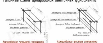
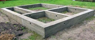
Slab foundations can be reinforced with a grid with a square cell in several tiers. And for foundation structures of strip, columnar, grillage or pile foundations, a spatial skeleton is assembled from individual rods.
A reinforced concrete foundation with a square/rectangular cross-section, as we noted above, experiences serious bending and tensile loads simultaneously from different sides. To get rid of cracks, the reinforcement must be as close as possible to the surfaces of the monolith, therefore one working rod is always placed at the corners of the cross-section of a strip or column foundation. That is, a minimum of 4 threads of reinforcement are used in the frame, in the area of each edge.
However, as the dimensions of the reinforced concrete product increase, it is also necessary to install intermediate reinforcement. The fact is that between the threads of the reinforcement cage there should be a distance of no more than 400 mm - this is stated in all industry design manuals. That is, if we have a shallowly buried strip foundation with a cross-section, for example, 500X300 mm, then the frame will consist of 4 rods. And if the cross-section of the foundation is, for example, 600X300 mm, then you will have to use 6 rods: 3 tiers of 2 pieces each.
As for the structural elements (these can be individual rods or “clamps”, which are rectangular “rings”), they should be placed at least every 60 centimeters.
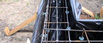
Reinforcement laying diagram
The reinforcement is laid and ready for pouring
Non-standard way of knitting the frame
To simplify the process of creating a metal frame as much as possible, you can build a simple device from scrap materials. It will not only significantly speed up mating, but will also help you cope with it without outside help.
Stage 1. Make four blanks from boards the length of the reinforcing bars and connect them two at a time at a distance equal to the length of the vertical jumpers.
Stage 2. Make improvised racks - stops on which you can place the resulting workpieces. The main thing is that they stand on a flat surface.
Step 3. Secure the tied boards. So you have a wonderful layout of the future frame, from which you can easily create a metal copy of it.
What is a mandatory protective layer, and how does it affect the placement of reinforcement?
We have already found out that the reinforcement should be as close as possible to the outer planes of the monolith; here it works as efficiently as possible. Meanwhile, there are strict restrictions on the permissible distance between the reinforcement cage and the outer surfaces of the foundation. The reinforcement must not be placed too close to the surface, otherwise there is a risk that the steel will be damaged due to corrosion (after all, concrete is to a certain extent permeable to water).
In addition, in order for the frame to work efficiently in the monolith, as a single whole with the cement stone, each rod must be reliably adhered to the concrete on all sides. Therefore, it is again very important to maintain a protective layer.
In numbers for a foundation structure buried in the ground, it looks like this (SNiP 2.03.01-84):
- If the foundation is poured without concrete preparation, then the protective layer should be more than 70 mm from the bottom.
- If the foundation is poured using concrete preparation, then the protective layer below should not be less than 35 mm. The same distance is maintained on top and on the sides of the monolith.
Another question is how to maintain the given distances in practice. To do this, under the lower bars of the reinforcing cage, linings of the required size (“crackers”, “clamps”) are installed. Ordinary construction waste, such as broken bricks, is not suitable, since when laying and vibrating a mass of heavy concrete, the frame can break such pads and sag. As a last resort, you can use pieces of durable hardened concrete, but it is best to use special plastic products that are fixed to rods of different diameters.
To create a protective layer between the reinforcement and the formwork panel, there are also factory-made polymer “crackers” (they are also called “spacers”). But here it is also allowed to use horizontal releases of metal rods, which, resting against the formwork, will ensure the correct positioning of the frame and a protective layer of concrete, respectively.
"Stool" for fittings
"Star" for fittings
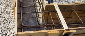
The process of creating a metal frame in formwork
Knitting a frame in a trench brings difficulties due to lack of space. But things will go quickly enough if you conveniently organize your workplace and get your hands on it.
Stage 1. You need to place stones approximately 5 cm thick at the bottom of the trench. They can be replaced with special plastic clamps for reinforcement.
Stage 2. Start by connecting the longitudinal rods and transverse rods. To make work easier, you can immediately tie vertical reinforcement blanks.
Stage 3. Then install the upper part of the frame.
Stage 4. First you need to make all the straight strip parts, and only then proceed to the corner connection.
Stage 5. In the corners the frame is subject to heavy loads. Using a larger diameter of reinforcement will help compensate for this.
How to connect reinforcing bars on straight sections and at corners?
Although reinforcement bars are available in fairly long lengths, sometimes they have to be spliced. No matter how carefully the connection is made, this node will always be weaker, so it should be located as far as possible from the corners of the foundation or, for example, from the middle of long walls. In addition, if it is necessary to splice adjacent rods, then the connections are arranged in a checkerboard pattern.
To securely fix the connected reinforcement, it is necessary to maintain sufficient overlap. The size of the overlap, according to current standards, should not be less than 20 diameters of the reinforcement, and in any case - not less than 25 centimeters. In some modern domestic manuals you can find a figure of 50 diameters, which practically meets the requirements of strict foreign standards.
Proper splicing of reinforcement
Incorrect splicing of reinforcement
The mutual fastening of the rods in the overlap is carried out using coupling connectors, crimping sleeves, spot or electric arc welding. You can also use annealed binding wire, which should be used to make at least three binding rings on the overlap.
There is a misconception that it is impossible to weld reinforcement when assembling frames, but this is not entirely true, it’s just that not everyone can do it correctly, and not every reinforcement is intended for this (if the marking contains the letter “C”, it means that the rod has increased strength and you can cook it).
In the area of outside corners and foundation T-joints, the reinforcement cage bars do not simply come into contact and cross each other.
Here it is also necessary to perform additional reinforcement with metal. This is done in compliance with the above requirements for organizing overlaps using auxiliary elements:
- Additional horizontal struts installed in small increments.
- Additional vertical elements holding together the tiers of the frame.
- Connecting L-shaped and U-shaped parts made of corrugated reinforcing rod of the same section as the main threads of the frame.
Reinforcement of junctions
Reinforcement of right angles
Reinforcement of turned corners
Useful tips
The fewer connections, the stronger the reinforcement frame. In addition, this will greatly facilitate the work and save expensive material.
It is more profitable to knit a metal frame with curved vertical struts than with separate pieces. This technology significantly saves money and effort spent on constructing the frame. You can bend the reinforcement on a special machine, or you can spend a couple of hours and do it yourself.
If you don’t know how to knit reinforcement for a frame and don’t have similar work experience, then it’s best to find help. This will not only make your work easier, but will also minimize injuries on the construction site.
As you have seen, creating a frame yourself is not that difficult.
The main thing is to make the right calculations and apply a little diligence. Related publications:
Where can I find “official” information on the correct reinforcement of monolithic foundations?
There is no single source. All the necessary information on methods of assembly and design of frames, as well as on the density of reinforcement, is available in numerous domestic regulatory documents, many of which were adopted back in the days of the Union. Let's list just a few of them.
- GOST 10884-94 Reinforcing steel thermomechanically strengthened for reinforced concrete structures.
- GOST 5781-82 Hot-rolled steel for reinforcement of reinforced concrete structures. Technical conditions.
- GOST 5781-82 Hot-rolled steel for reinforcement of reinforced concrete structures. Technical conditions.
- GOST-2590–2006 Hot-rolled round steel products. Assortment.
- GOST 23279-85 Welded reinforcement mesh for reinforced concrete structures and products.
- SP 52–101–2003 Concrete and reinforced concrete structures without prestressing reinforcement.
- SNiP 2.03.01-84 Concrete and reinforced concrete structures.
- GOST 14098-91 Welded connections of reinforcement and embedded products.