What determines the optimal tape width?
The cross-sectional dimensions of the strip foundation are determined by design calculations and depend on factors such as:
- soil type at the construction site;
- soil freezing depth;
- groundwater level;
- calculated weight of the building taking into account snow cover;
- wind loads on walls and roofs;
- the material from which the foundation will be built.
To collect initial data, it is necessary to use reference literature and conduct hydrogeological surveys on the site.
Tape and sole width - what's the difference?
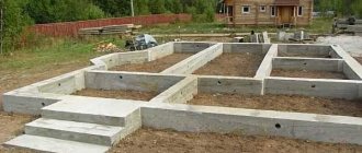
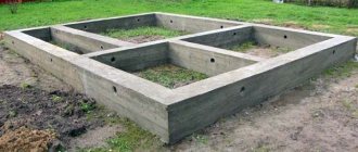
A traditional strip foundation is built on a base - a platform made of reinforced concrete, which is needed to evenly distribute the load from the strip onto the ground.
Without a sole, such a load will be excessive, and the foundation will sag. To properly distribute the weight of the base, the sole should be wider than the tape itself, usually twice as wide .
What determines the width of the sole? This figure may increase for loose, sandy or silty soil. The standard width of the sole is 60 cm, but this parameter is not universal, since it all depends on the width of the base tape. As for the height of the sole, it is usually 30 cm.
Regulations
The width of the strip foundation is primarily tied to the bearing capacity of the soil. For dense, stable soil, it is enough to add 70-100 mm on each side of the wall thickness to obtain the optimal tape width. But in case of loose and loose soil, it must be significantly increased - in some cases it can reach 900 mm.
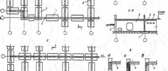
To avoid high consumption of concrete or stone materials, composite structures are used from a wide concrete support at the bottom and the upper part of the tape, the width of which depends on the thickness of the walls. The main problem of wide strip foundations is the impossibility of their use on mobile heaving soils and high groundwater levels.
There are three regulatory documents that should be used when performing calculations:
- SNiP 2.01.07-85 – Loads and impacts;
- SNiP 2.02.01-83 – Foundations of buildings and structures;
- SP 131.13330.2012 – Construction climatology.
The first outlines the methodology for calculating the foundation. The second provides standard requirements for foundation structures. The third indicates the depth of soil freezing in climatic zones for most large populated areas.
It is possible to obtain data on the depth of groundwater and determine the type and structure of the soil only on the basis of hydrogeological surveys on the site. They are carried out by specialized organizations, carrying out test drilling to a depth below the freezing point. This service is not cheap, but you need to use it, because they do not skimp on reliability and security.
Input data.
House with an attic, wooden frame structure on a strip monolithic reinforced concrete foundation.
Frame house
Composition of the premises: 1 room - 9.47 m2, 2 room - 6.30 m2, 3 kitchen - 6.30 m2, 4 veranda - 9.47 m2, 5 attic - 12.15 m2. Height to ceiling 2.65 m. Roof area 55 m2. The windows are wooden, double. External doors are metal, internal doors are wooden.
The construction of the house is expected on loamy soils with a freezing depth of up to 1.0 m. The distance from the planning mark to the groundwater level, during the period of soil freezing, is less than the calculated freezing depth. Place of construction - Kharkov region.
We set the preliminary parameters of the foundation based on the existing geological conditions and the adopted layout scheme.
Foundation diagram (6.0 m x 6.0 m).
Based on our conditions. We accept the preliminary geometric dimensions of the foundation: width - 0.4 m; height – 1.1 m. Total area of the foundation base: length 30 m x width 0.4 m = 12 m2.
Structural elements and materials used:
- foundation – reinforced concrete strip, monolithic;
- base – brick;
- walls - wooden frame with outer cladding made of clapboard;
- doors: external - metal,
- internal – wooden;
Minimum width
The method for calculating the dimensions of the ribbon section does not determine the specific numerical value of the width, but the value, less than which it should not be. The actual foundation is usually 10-20% larger, and the minimum width of the strip foundation is needed to determine the optimal width and reduce construction costs.
Sometimes, when the soil is dense and stable and the calculations require a minimum foundation width of 200-250 mm, a compromise option is used. The lower part is built narrow, and the upper 300-400 mm is determined by the thickness of the walls. This method can often be seen in the construction of light baths, verandas and outbuildings.
Methods
Various methods are used for calculations. One of them is the calculation of strength and stability. It is based on the calculation of the bearing capacity of the foundation.
This technique is used in certain cases - if the construction of the building will be carried out:
- on the slope,
- on rocky ground,
- in areas with strong seismic influence.
Calculations are performed using a chain of complex formulas and are carried out by qualified specialists.
There is a method for calculating strip foundations based on the bearing capacity of the soil.
It is a calculation of the minimum area of the base of the tape, at which the building together with the base will not push the soil underneath and sag. Calculating the width of the tape and the width of the foundation base will be discussed in more detail below . For such evictions, a table of soil bearing capacity is used.
Instead of calculations based on the bearing capacity of soils, which are used more often and are simpler, calculations based on the soil deformation modulus can be used. This is a more complex engineering process carried out using complex formulas.
Maximum width
In the above regulatory documents there is no concept of the maximum width of the foundation strip. The design calculation of the width of the strip foundation should be aimed at the opposite - determining the optimal dimensions in order to reduce financial costs.
However, there is one important nuance that should be taken into account when constructing buildings with a basement. In these cases, there is a limitation on the maximum width of the foundation. It is related to the weight pressure on the ground and depends on the length of each individual wall, as well as the material from which it is made.
For walls up to 3 meters long, the foundation base should be no more than:
- concrete monolith – 400 mm;
- concrete foundation blocks – 500 mm;
- rubble concrete – 600 mm;
- solid brick – 750 mm;
- rubble stone – 800 mm.
If the walls are more than 3 meters long, then the maximum allowable width is:
- reinforced concrete monolith – 500 mm;
- concrete foundation blocks – 600 mm;
- rubble concrete – 800 mm;
- solid brick – 900 mm;
- rubble stone – 1000 mm.
This data is not a regulatory requirement and is taken from practical observations of builders. Therefore, they should be taken into account in calculations, but not taken as unconditional.
What data will be required for the calculation?
In addition to the climatological indicators of the region, the hydrogeological structure of the soil and the determination of the material of the foundation walls, to develop the project it is necessary to determine the total weight of the building, the bearing capacity of the soil and the length of the walls.
Determination of building load
The weight load on the strip foundation is determined by a simple formula:
M+P+S+V , where:
- M – dead weight of the building, including the weight of all building structures and elements, including the foundation;
- P – payload or weight of everything that will be inside the building and create pressure on the floors;
- C – maximum possible mass of snow cover in winter and at the beginning of melting;
- B – wind pressure on walls and roof.
The resulting calculated result should be multiplied by a factor of 1.2-1.25, providing a 20-25% safety margin for the strip foundation structure.
Bearing capacity or soil resistance
This indicator is given in the regulatory literature and is determined by GOST 25100-95 “Classification of soils”. For the most common soil types it is (in kg/cm2):
- loam – 1.5-2.8;
- dry dense clay – 1.6-3.0;
- fine-grained sand – 2.2-3.4;
- medium-grained – 2.5-3.6;
- sandy loam – 2.6-3.6;
- coarse sand – 3.6-4.6;
- gravel, crushed stone, pebbles – 5.1-6.5.
The indicator of resistance to weight loads is also affected by soil moisture, fluidity and porosity, which must be taken into account when preparing calculation data.
How to create a strip foundation with your own hands
Before starting work, you should stock up on everything necessary for the current production stages, and also think over and agree on the delivery of materials for all subsequent ones. For example, you will need:
- thick film of polyethylene, propylene or roofing felt - for waterproofing layers;
- wooden blocks, boards, plywood, nails, screws - for formwork;
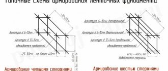
- reinforcement, knitting wire - for reinforced frame;
- river sand, fine crushed stone - for preparing the bottom of the trench, creating a “cushion”;
- concrete solution - for forming the tape. You can prepare it on site on your own; therefore, you will have to additionally import sand, crushed stone and cement, or order a ready-made one from the manufacturer with delivery to the desired address.
An example of calculating the width of the sole for a strip foundation
The size of the supporting foundation sole is determined using the formula:
Width = mass of building: length of walls: soil resistance
Let's assume that the initial calculations during data collection showed:
- a building made of aerated concrete blocks, taking into account the useful, snow and wind loads, creates a weight pressure of 165,800 kgf;
- the total length of the foundation strip in a house of 10 x 8 meters with one transverse lintel is 44 meters or 4400 cm;
- soil – dry dense clay with a bearing capacity of 1.9 kg/cm2.
Based on these indicators, we calculate the width of the tape for a house made of aerated concrete:
165800: 4400: 2.1 = 19.83 cm, rounded to 20 cm
It turns out that the minimum width of the tape can be 20 cm. However, the thickness of the aerated concrete blocks is 300 mm and the foundation must protrude beyond the edges of the wall by at least 5 cm. Therefore, the optimal width of the sole will be 400 mm, which will provide a double margin of structural strength. By the way, a complete calculation of the tape base is presented here, and the issue of the optimal depth of the tape is discussed here.
Foundation design and calculations
Having a project for your future home, you need to correctly calculate the base. To perform all calculations on the Internet, there are a sufficient number of computers that facilitate this work in real time. It is only necessary to determine the characteristics of the soil at the construction site, in particular, its bearing capacity, freezing depth, and the position of groundwater.
It is also necessary to calculate the weight of the future building, for which the tables are the density values of the materials used in the construction of the building. The mass of walls, floors, roofs, finishing materials, snow load, furniture, household appliances, etc. is calculated.
The result should be the total weight of the building transferred to the ground using piles, and this value should not exceed the load-bearing capacity of the building.
As a starting point for the project, round reinforced concrete pipes with a diameter of 30 cm can be laid in 1 meter increments. Whether it is necessary to increase or decrease the number of piles and their diameters, and the calculation is derived.
Find out how to make a pile-strip foundation: //6.com///-Pile.html

