Step 1. Parameters of the designed foundation
Menu item: The width of the foundation is unknown (determined by the method of successive approximations)
If you do not know the width of the foundation being designed, or you want to know the minimum allowable width of the foundation, then select this menu item.
In this calculator, the width of the base of the foundation and the edge (the upper base of the foundation) are the same.
The foundation width will be calculated using the method of successive approximations. There are several ways to implement it. The longest (if counted by hand) but easiest to understand method was chosen. Initially, the calculated resistance of the foundation soil [R] and the average pressure along the base of the foundation are determined
with a foundation width of 0.1 meters, and the fulfillment of the condition [p<=R] is checked. If the condition is not met, then the width of the foundation increases by 0.1 and so on until the condition is met.
Menu item: The width of the foundation is known (set structurally)
If the width of the foundation is specified structurally, then select this menu item.
If the condition [p<=R] is not met for a given width, the calculator will issue a warning and display the minimum allowable width of the foundation at which this condition will be met.
Field: Foundation Width
If the menu item “The width of the foundation is known (set structurally)” is selected, enter the value.
If the menu item “Foundation width is unknown (determined by the method of successive approximations)” is selected, the field becomes inactive. The unit of measurement is meters.
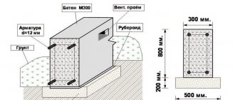
Field: Foundation depth
Enter the value of the foundation depth. The unit of measurement is meters.
The depth of the foundation, as a rule, is the distance from the planning level to the base of the foundation.
The depth of the foundation will depend on 4 main factors:
- Geological. A solid layer of soil must be used as the base. It is necessary to provide for the foundation to be immersed 10-15 cm into the load-bearing soil layer.
- Constructive. The depth of installation is designed taking into account the design features of the building (structure): the presence of a basement, underground, communication lines, etc.
- Climatic. Dependence on the depth of soil freezing. To calculate this indicator, you can use the calculator: Calculation of the standard and estimated depth of soil freezing.
- Hydrogeological. The relationship between the groundwater level and the estimated depth of soil freezing.
In suburban construction, two main types of foundations are used: shallow foundation (MZLF) and buried below the depth of soil freezing.
To calculate the MZLF, you can use some methods. For example, Sazhin’s book: Don’t bury the foundations deep. Average laying depth: 0.5 m Advantages of this type: lower consumption of concrete, less influence of tangential forces during soil heaving (for heaving soils).
Field: Foundation height
Enter the height of the foundation. The unit of measurement is meters.
With a known foundation depth, we determine the height of the above-ground part and add up both values. The height of the above-ground part is specified structurally.
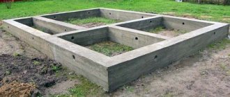
Foundation calculation. Tape length
The online calculator includes a strip configurator, which can be used to configure a strip foundation scheme that suits you. If suddenly you don’t find your option, you can calculate the length of the tape yourself and enter your values. How to do this will be described below.
List: Add parallel axes between A-G
We select the number of axes that will be added between axes A and D. New axes will be laid parallel to axes A-G. You can add up to 2 new axes.
If selected:
0 – there are no additional axes between axes A-D. We have a foundation without internal load-bearing walls.
1 – there is one additional axis B between axes A-D. When choosing this option, two lists become available: “Add perpendicular axes between A-B” and “Add perpendicular axes between B-D”.
2 – between axes A-D there are two additional axes B and C. When choosing this option, three lists become available: “Add perpendicular axes between A-B”, “Add perpendicular axes between B-C” and “Add perpendicular axes between B- G".
List: Add perpendicular axes between B-G
We select the number of axes that will be added between axes B and D. New axes will be laid perpendicular to axes B-D. You can add up to 2 new axes.
List: Add perpendicular axes between A-B
We select the number of axes that will be added between axes B and D. New axes will be laid perpendicular to axes B-D. You can add up to 2 new axes.
List: Add perpendicular axes between B-C
We select the number of axes that will be added between axes B and C. New axes will be laid perpendicular to axes B-C. You can add up to 2 new axes.
List: Add perpendicular axes between B-D
We select the number of axes that will be added between the B and D axes. The new axes will be laid perpendicular to the B-D axes. You can add up to 2 new axes.
Flag: L-shaped foundation
When you check the box, the diagram of the L-shaped foundation strip will be considered. When you select the checkbox, two fields will become available to indicate the dimensions of the new part of the foundation.
Foundation dimensions
When specifying dimensions, it is worth paying attention to the fact that dimensions must be indicated along the outer boundaries of the foundation. That is, the axes do not pass through the middle of the tape, which is more common, but along the outer boundaries of the foundation. Choosing this option for specifying dimensions simplifies the calculation of the foundation with an unknown tape width.
Field: Length A-G
We indicate the dimensions between axes A-D. The axes run along the outer edges of the foundation.
Field: Length 1-2
We indicate the dimensions between axes 1-2. The axes run along the outer edges of the foundation.
Field: Length A-E
We indicate the dimensions between axes A-E. The axes run along the outer edges of the foundation.
Field: Length 2-3
We indicate the dimensions between axes 2-3. The axes run along the outer edges of the foundation. Since axis 2 is common to 1-2 and 2-3, we consider this:
- We determine the distance between axes 1-3 (along the outer boundaries of the foundation).
- We enter dimensions 1-2 (along the outer boundaries of the foundation).
- The distance between axles 2-3 will be the difference between dimensions 1-3 and 1-2.
Checkbox: Set the tape length yourself
If you did not find your option in the tape configurator, you can specify the tape length you calculated yourself. If the checkbox is checked, the calculation will be carried out only based on your length values.
Menu: Calculation of concrete and reinforcement for the foundation
Menu item: No calculation required
When selecting this type of menu, the results will not indicate the calculation of concrete and reinforcement for the designed foundation.
Menu item: Calculate the total amount of concrete and reinforcement
When you select this menu item, the fields for selecting reinforcement and parameters for calculating concrete for the foundation become active.
Menu item: Calculate the total amount of concrete and reinforcement + concrete composition
When you select this menu item, the results will display calculations of reinforcement, amount of concrete and concrete composition calculated from the input data.
The calculation of concrete was carried out according to the method described in the book by V.P. Sizova: Guidelines for the selection of heavy concrete compositions.
The calculation algorithm can be viewed on the page of the Beton-Online calculator v.1.0
Menu item: Calculate the total amount of concrete and reinforcement + concrete composition + number of batches in a concrete mixer
When you select this type of menu, the “Concrete Mixer” field becomes active, where you must specify the volume of the concrete mixer for mixing concrete.
When you select this menu item, the results will display calculations of reinforcement, amount of concrete, concrete composition, and calculations based on the number of batches in a concrete mixer.
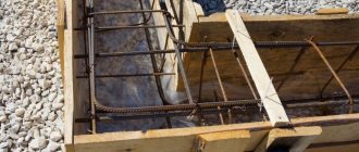
Reinforcement calculation
Menu item: The number of longitudinal reinforcement bars on the strips is known (specified structurally)
When you select this type of menu, the following fields become active: “Diameter of reinforcement” and “Number of longitudinal bars”.
If you have a calculation of reinforcement for the tape and you know the diameter and number of longitudinal bars, then select this type of menu. The total number of rods in the section of the tape is indicated. That is, if you have 2 rows of 2 rods in each row, then indicate 4.
Menu item: The number of reinforcement bars is not known (the number of working longitudinal reinforcement will be calculated according to SP 52-101-2003)
When this menu type is selected, the “Number of longitudinal bars” field becomes inactive.
You will only need to indicate the diameter of the reinforcement and the calculator will calculate the number of rods according to the standards of SP 52-101-2003.
If the cross-section of the tensile reinforcement is below 0.1% of the ribbon cross-section (the minimum allowable according to SP), then you will see a warning in the results: The reinforcement cross-section is less than the minimum. It is necessary to increase either the diameter of the reinforcement or the number of rods.
When selecting this type of menu, we can only increase the diameter of the reinforcement and check again. If no warning appears, then the diameter is selected correctly.
Field: Reinforcement diameter
Select the diameter of the reinforcement. The following diameters are available for selection: 10, 12, 14, 16, 18, 20, 22, 25, 32, 36, 40mm. For tape in suburban construction, 10-12mm is mainly used for longitudinal reinforcement, and 6-8mm for transverse reinforcement (clamps).
Field: Number of longitudinal bars
We select the number of longitudinal rods per section of the tape. The field is active when selecting the menu item: “The number of longitudinal reinforcement bars for the strips is known (specified structurally)”
Concrete calculation
We fill in all lists and fields to obtain the quantity and composition of concrete. The calculation algorithm can be viewed on the page of the BetonOnline calculator v.1.0
Cost of fittings
Reinforcement can be purchased at construction stores. Its quantity is calculated in linear meters. Therefore, in order to find out how many meters are required and calculate the final price, you need a table of rental weight. Next, we calculate using the formula: (number of metal rods in running meters) and multiply by (weight of 1 running meter of rods for the corresponding diameter) multiply by (cost of 1 ton of rods)/1000.
The weight of the reinforcement depending on the cross-section can be seen in the table:
| Reinforcement diameter | Kilogram in 1 meter | Meters to kilograms | Meters in 1 ton |
| Armature 5 | 0,187 | 5,347 | 5347 |
| Armature 6 | 0,222 | 4,5045 | 4504 |
| Armature 8 | 0,395 | 2,53165 | 2531 |
| Armature 10 | 0,617 | 1,62075 | 1620 |
| Armature 12 | 0,888 | 1,12613 | 1126 |
| Armature 14 | 1,21 | 0,82645 | 826 |
| Armature 16 | 1,58 | 0,63291 | 633 |
| Armature 18 | 2 | 0,5 | 500 |
| Armature 20 | 2,47 | 0,40486 | 405 |
| Armature 22 | 2,98 | 0,33557 | 335 |
| Armature 24 | 3,85 | 0,25974 | 260 |
| Armature25 | 4,83 | 0,20704 | 207 |
| Armature 28 | 6,31 | 0,15848 | 158 |
Reinforcement with a diameter of 12 mm and a corrugated or smooth surface is in great demand. It can be sold in rods and coils.
The approximate price for 12 mm diameter per 1 m can be found in the table:
| Name | Price per meter, rub |
| A1 12 mm | 21,78 |
| A3 A400 12 mm | 21,05 |
| A3 A500S 12 mm | 21,05 |
| A3 25G2S 12 mm | 22,98 |
| 35GS 12 mm | 22,7 |
Reinforcing a strip base is not at all difficult, although it is a fairly energy-intensive process that requires financial investment. But saving doesn't make sense. By choosing the right reinforcement and calculating its quantity, you can strengthen the foundation, while extending the life of the entire building.
You can watch an example of independent calculation of a strip foundation in the video:
Comments
03/24/2016 20:59:18 Unogroup
Calculation of reinforcement The number of reinforcement bars is not known (the number of working longitudinal reinforcement will be calculated according to SNiP 52-01-2003) specified 12 reinforcement with a tape width of 50 cm did not want to increase the number of rods to 6. says 4 rods, increase the diameter a little. When manually specifying 6 rods, 12 says that everything is ok. The loads on the foundation that need to be set without taking into account the weight of the foundation itself are not obvious to an amateur like me, but a professional can calculate it without a calculator. Who, when the load per linear meter of the foundation is 8 tons, says that you need a tape 70 cm wide when 12 already wants 90. seems like overkill. Roughly we take a box of 13x10 meters with 1 carrier in the middle. 2.9 tons of voids were placed on the foundation; 1.5 meter Pk63x15 per meter is supported by 1.9 tons/2 on the external walls and 1.9 on the central one. on it the residential load is 500 kg per square meter. to the central 6*0.5 3 more tones. already 4.9 tons. on top of the gas block d500 3.3 m * 0.3 m wide = 0.5 tons. armored belt 1.8*0.2*0.3=0.1 t. + again voids 1.9 4.9+0.5+0.1+1.9=7.4 tones and that’s just the attic. add 0.2 * 6 = 1.2 attic load + 0.25 * 8 = 2 snow wind load + the weight of the roof itself has already reached 12 tons per linear meter. And this is the 1st floor made of lightweight aerated concrete; I have never seen a foundation strip 90 cm wide for such houses. Is there a mistake in the calculator somewhere or did I collect the loads incorrectly?
Answer
03/24/2016 20:59:29 Maxim Gvozdev
Unogroup, thanks for testing the calculator! 1. Reinforcement is still considered at the minimum: 0.1% of the tape cross-section (according to SNiP). The algorithm for calculating rods is described below the calculator in the explanations. 2. Regarding the collection of loads on the foundation. Well, in general the field is called “Vertical load on foundation [N], kN/m”. But I agree that not everyone will understand. For now I just added in the explanations to the calculator that the calculation of loads does not take into account the foundation. Now I’m going to create a section in the calculator where you just need to indicate the materials of the house’s construction and the calculator will automatically calculate the loads. Everything should definitely be clear there. 3. 12 t/m is 120 kN/m. If the width of the foundation is unknown, the calculator gives a width of 0.7 m. Taking into account that we have the default soil (step 2). Or did you have other input parameters?
03/24/2016 20:59:57 Unogroup
An 11x14 house with 1 load-bearing structure in the middle did not change the soil. depth 0.8 above ground 0.4. with a load of 120 kn/m it gives a belt width of 90 cm. 70 wants already at 80 kn/m. somehow I didn’t notice a difference when changing the type of soil
Answer
03/24/2016 21:00:07 Maxim Gvozdev
Yes I see. Well, in general it is 0.9 m. Here this width turns out to be due to the low design resistance of the soil. Total 174kPa. I have calculations below the results. You can see where each number comes from and what formula is used. The calculation shows that the soil resistance is affected by the depth and the tabulated soil resistance Ro (Appendix B SP 22.13330.2011). Well, we do not take the width of the foundation, since it is calculated on the condition that it is unknown (in the calculations you can also see how the width of the foundation is calculated). If you increase the laying depth or change, for example, in step 2, the fluidity index of loam (select 0), this will lead to a decrease in the width of the tape, as the soil resistance will increase.
03/24/2016 21:00:22 Lehavan
Good afternoon It's working out well! What is still missing is the function of changing the width of the foundation lintels relative to the load-bearing ones, and accordingly changing the number of longitudinal reinforcement bars in them
Answer
03/24/2016 21:00:31 Maxim Gvozdev
Lekhavan, thank you for your interest in the calculator. In terms of loads, if you disassemble a five-wall structure, the internal load-bearing wall will bear a greater load than the external ones. Self-supporting ones are less than external supporting ones. The lintels under the partitions have the least load. If you take a separate house project, you can calculate the width of the tape for each wall and design the reinforcement. It is still difficult to take all this into account in a calculator (although everything is possible). And the calculator will turn into a good program for calculating tape with a large number of input parameters. Still, I would like to make a more universal tool and simple enough for a non-specialist. It is worth considering that loads can be distributed relatively evenly over the foundation for a given house structural rigidity. Now I’m making a calculator for collecting foundation loads from a house. There I plan to collect loads both evenly distributed over the entire foundation, and separately along the load-bearing walls.
03/24/2016 21:00:46 gen555
First of all, thank you for your hard work! And secondly, there is a question: for my calculation it produces the phrase “For foundations, it is recommended to use longitudinal working reinforcement with a diameter of 12 mm or more.” In my project (it seems to be calculated), all the reinforcement, except for the ties, is d10. Can you tell me what document this recommendation is from? SP 52-101-2003? Or is it obtained as a result of calculation?
Answer
03/24/2016 21:00:59 Maxim Gvozdev
@gen555, the calculation gives the required cross-sectional area of the reinforcement. Then you can select the number of reinforcement bars of the required diameter so that the design requirements described in SP 52-101-2003 are met. But there are also recommendations for reinforcing reinforced concrete structures and foundations. More details can be found on the page with a reinforcement calculator: https://www.gvozdem.ru/stroim-dom/kalkulyatory/armirovanie-lentochnogo-fundamenta.php Let’s just say that for the foundation it is preferable to use working longitudinal reinforcement with a diameter of 12 mm or more, if you don’t want to delve into the study of literature and calculations.
04/09/2016 14:34:09 Sergey
Good afternoon First of all, I would like to thank you for this calculator and the most detailed presentation. Could you answer this question: if we consider a high tape (1.7 + 0.3), then the upper and lower belts should each contain 6 longitudinal rods. With a minimum distance between the bars of 25 cm (SNiP) and a tape width of 40 cm, what will the belt look like?
Answer
04/12/2016 13:53:42 Sergey
Most likely, because of a stupid question, I never received an answer, but the intended goal of gaining knowledge in this area led me to the conclusion that I was confused somewhere and did not perceive it correctly. Because I really liked the calculator and the site as a whole, I would like to share new (for me) data here: “The minimum distance between the longitudinal reinforcement bars cannot be less than the largest diameter of the reinforcement bars and at least 25 mm for the bottom row of reinforcement and 30 mm for the reinforcement top row with two rows of reinforcement. With three rows of reinforcement, the distance between the reinforcement bars in the top row should be at least 50 mm. In case of high saturation with reinforcement, separate places should be provided with a distance between the reinforcement bars of 60 mm for the passage of the tips of deep-seated vibrators between the reinforcing bars, compacting the concrete mixture.” Thus, in the upper belt you can safely place the reinforcement at a distance of 3-5 cm from each other, thereby solving the above problem. In general, the task arose due to the availability of the 12th reinforcement (almost for nothing), with all that it implies. If it is useful to someone, I will be glad. Please correct me if I'm wrong.
04/12/2016 15:08:00 Maxim Gvozdev
Sergey, please forgive me for delaying my answers. I am not a designer. I'm just studying SNiPs and other technical regulations. documentation and trying to automate what can be automated. I have created topics for each calculator on the large construction forum forumhouse.ru where there is a discussion about each calculator. The topic for this calculation is presented on this page: https://www.forumhouse.ru/threads/302227/
Construction calculators
- Concrete-Online calculator v.1.0 - calculation of concrete composition.
- Calculator Mortar-Online v.1.0 - calculation of the composition of mortar for masonry work.
- Calculator GruntSopr-Online v.1.0 - calculation of soil resistance of the foundation.
- GPG-Online calculator v.1.0 - calculation of the standard and estimated depth of soil freezing.
- Calculator Stolby-Online v.1.0 - design of a columnar foundation.
- MZLF-Online calculator v.1.0 - calculation of a shallow strip foundation (MZLF).
- Weight-House-online calculator v.1.0 - calculation of loads on the foundation.
- Calculator Reinforcement-Tapes-Online v.1.0 - calculation of reinforcement for strip foundations.
Reinforcement calculation
Next, you need to calculate how much material will be needed for reinforcing work. For example, the diameter of the steel rod will be 12 mm, according to the plan in the casting there will be 2 horizontal rods, and vertically, for example, the rods will be located in increments of 0.5 m. The perimeter is 27 meters. So, 27 must be multiplied by 2 (horizontal rods) and the result is 54 m.
We count vertical rods in a similar way: 54/2 + 2 = 110 rods (108 intervals of 0.5 m each and two on each side). To take into account the rods at the corners, you need to add 1 more rod , it turns out 114. If we take the height of the rod -70 cm, we calculate the length of the material: 114 x 0.7 = 79.8 m.
The easiest way to calculate the reinforcement for a strip foundation is to use an online service - a calculator.