Tape is a basic type of foundation that has the best balance of cost-effectiveness, simplicity and high load-bearing capacity.
The properties and capabilities of strip foundations have been studied in detail and tested over many decades of active use; rich operation statistics have been collected, allowing one to analyze and study the behavior of the supporting structure in any conditions.
In addition to its own capabilities, the tape can be combined with other types of supporting structures, resulting in a significant increase in load-bearing capacity and expansion of application areas.
One example of the most successful connection is a pile-strip foundation, which solves a lot of problems with the stability of the supporting structure and allows it to be used on difficult soils. Let's take a closer look at this option.
What is a pile-strip foundation
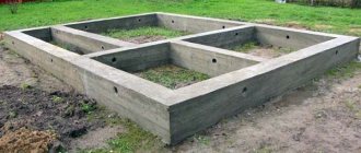
A pile-strip foundation is a supporting structure consisting of a system of piles immersed in the ground until contact with dense layers appears. The piles are tied with a concrete tape, which takes the load from the weight of the house and distributes it evenly between the piles and the ground.
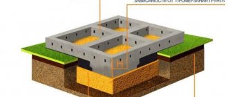
The depth of immersion of the tape is small, corresponds to the usual parameters of shallow-depth tape bases.
Piles, on the contrary, are immersed below the freezing level of the soil to ensure strong and immovable support.
Both elements are rigidly connected to each other, forming an inseparable strong support for the house.
The reinforcing belt of the tape and piles is a single system. if screw or submersible piles are used, the armored belt is rigidly connected to them by welding.
IMPORTANT!
In this case, the load is evenly distributed between the piles and the tape; individually they are not able to cope with the weight of the buildings and the soil pressure.
How to calculate the number of piles for a foundation
Correct calculation of the number of piles used requires preliminary geodetic survey. First of all, it is necessary to calculate the level of soil freezing in winter, taking into account that this indicator differs in different regions. To install the pile firmly, its lower end must be below this level.
It is also necessary to find out the degree of density of the soil layers. The higher the density, the shallower the depth of the pile should be laid at the design stage. For example, for semi-rocky and large-block rocks it will be minimal (but not less than 0.5 meters), and for sandy and clayey soils it will have to go as deep as possible.
To calculate the number and type of piles used, many parameters must be taken into account. To simplify the task, you can use a special online calculator, but for a general understanding of the process, it is better to go through all the stages of the calculation yourself.
1. Calculation of the potential ultimate load on piles
Before you start calculating the number of piles for the foundation, you should find out the bearing capacity of an individual pile. The general form of the formula is as follows:
In this case, W is the desired actual load-bearing force, Q is the calculated value of the load-bearing force, calculated for an individual pile based on the material, dimensions and characteristics of the soil; k is an additional “reliability factor” that expands the operational reserve of the foundation.
2. Calculation of the design load on piles
Next, we need to find the parameter Q, without which the calculation of a pile foundation is impossible. The design load is determined by the formula:
Where S is equal to the cross-sectional area of the pile blades, and Ro is an indicator of soil resistance at the depth of the blades. Soil resistance can be taken from the prepared table:
table 2
As for the “reliability coefficient” of a conditional foundation, its value can vary between 1.2-1.7. It is logical that the lower the coefficient, the lower the cost of the foundation at the design stage, since the use of a large number of piles will not be required to achieve a given value of the bearing force. To reduce the coefficient, a high-quality and reliable analysis of the soil at the construction site should be carried out, involving specialists.
And also for these purposes, the technique of screwing in a reference well is used. Its use is often required to calculate the settlement of pile foundations on industrial construction sites and during the construction of multi-apartment buildings, as required by SNiP. But if desired, a reference well can also be drilled during individual construction.
3. Calculation of the load from the building structure
At the final stage of designing a pile foundation, the number of piles is calculated. To do this, you will need to summarize all the structural elements of the building: from the main walls and ceilings, to the rafter system and roof. It is quite difficult to accurately calculate all components, so we recommend using one of the specialized calculators. And also operational loads are entered into the calculation calculator, including interior items, furniture, household appliances and even people living in the house.
4. Calculation of the required number of piles
Before calculating the number of piles involved, we need to obtain two values at the previous stages: the total mass of the building (M) and the load-bearing capacity of the pile (W) multiplied by the “reliability factor”. The value of the bearing capacity can be taken from Table 1. So, if the mass is 58 tons, and the adjusted bearing capacity of the SVS-108 pile is 3.9 tons, then:
As the calculation example showed, for a house weighing 58 tons, 15 piles of the SBC-180 grade will be required. It should be noted that this value is approximate and does not take into account the rules for the exact distribution of piles according to SNiP:
- The first should be installed at the intersection points of load-bearing structures;
- The rest are mounted evenly between the designated corners;
- The minimum distance between individual piles is 3 meters;
As a rule, during the design process it turns out that to comply with the above rules, a little more piles will be required than the calculations showed.
5. Installation depth of piles and distance between them
The basic value of the installation depth of the pile is calculated based on the depth of soil freezing in a particular region, plus 25 centimeters. And also before calculating the pile foundation, you need to find out:
- Pile strength level by material and design;
- Bearing capacity of the soil;
- Calculate the settlement of the pile foundation that occurs over time under the load of the building;
- Additional parameters (temperature conditions throughout the year, precipitation volume, wind loads, etc.).
Advantages and disadvantages
The advantages of pile-tape foundations include::
- Possibility of use on problematic soils.
- To build such a foundation, a relatively small amount of building materials is required.
- High resistance to soil influences - heaving, small movements.
- Some types of piles can be created directly on site, which can significantly reduce the cost of purchasing, delivering and driving them into the ground.
- It becomes possible to build in areas with high groundwater levels.
- High speed of construction.
There are also disadvantages:
- Before starting construction, it is necessary to carry out a thorough comprehensive survey of the site regarding the composition of the soil, the height of groundwater, etc.
- There is no possibility of creating a basement or basement.
- High-quality insulation of the floor of the lower floor laid on the ground is necessary.
- There is no possibility of constructing multi-storey buildings.
- Piles must be properly waterproofed. This is especially true for wooden or steel supports.
Most of the disadvantages are in one way or another due to the properties of the soil , so in this case these are not exactly disadvantages of the foundation, but necessary limitations in the existing conditions.
Calculating the number of screw piles using a calculator
- Specify the length of the sides of your building, choosing a shape from 3 to 15 meters.
- Indicate the type of building - house, garage, household building, etc.
- Indicate “number of floors” if the corresponding columns appear. When filling out the columns, please note that a house with an attic will be considered a one and a half-story building.
- Choose the material for your building.
- Indicate the type of soil on the site.
- Indicate the number of corners of the planned house.
- Specify the height of the basement floor from the proposed options.
- Please indicate whether you are going to install a fireplace/stove.
- Click “Calculate”.
In a few seconds, the result of calculating the required number of piles for your object will appear.
Let's look at an example
There is a peat area with a peat depth of 3 meters. You have decided to build a wooden house (timber 150x150), with an area of 10 by 10 meters. The house is planned to have an original shape with nine corners and an attic. The floor will be located at a height of 50 cm above the ground. To keep you warm in winter, it was decided to install a fireplace in the house.
After all the data was entered, the calculator for calculating the number of screw piles gave us the result - 32 piles, with a diameter of 108 mm and a length of 4.5 meters.
Of course, this calculation is preliminary. It serves as a guide when planning your budget and further orders. For a more accurate result, it is necessary for a specialist to visit the site for a detailed inspection of the site for the planned development, where all factors will be taken into account.
Scope of application
The pile-strip foundation is suitable for the construction of private low-rise buildings.
Large multi-story buildings that are heavy require stronger support . The dimensions of the piles for them must be increased, and the load-bearing capacity of the tape becomes unnecessary.
For heavy buildings, a similar option is used - a pile-grillage foundation.
They have almost the same structure, but these two types cannot be confused , since in a pile-tape foundation the load is equally divided between the tape and the piles, while in a pile-grillage foundation the load-bearing elements are piles, and the grillage only distributes and transmits the load.
The type of foundation under consideration is the optimal compromise option for constructing a belt on problematic soils with additional reinforcing elements, but without the use of complex and labor-intensive work.
What soils are they used for?
Pile-strip foundation is used on complex and problematic soils of various types:
- Loose.
- Possessing a complex composition and layering.
- With a high groundwater level.
- With multiple moisture-carrying layers.
- Heaving.
In addition, a pile-strip foundation performs well when constructing on slopes or folds of relief, when it is impossible to carry out large excavation works for a number of reasons. In such situations, the decisive factor is not the composition of the soil, but the shape of the relief , which dictates its conditions for choosing a foundation.
Types of pile-strip foundations
All types of pile-tape foundations differ in the type of piles used in conjunction with the tape.
Exist:
- Screw . Metal pointed pipes with blades installed at the bottom. They are immersed by screwing into the ground using the principle of a screw. Allows you to operate manually in close proximity to neighboring buildings.
- Bored . The piles are poured directly on the site. For pouring, a well of the required depth is prepared, into which the reinforcement frame and waterproof formwork (polyethylene or asbestos-cement pipes) are lowered. Sometimes the walls of the well are used as formwork (if the soil allows).
- Submersible . Ready-made piles are used, which are driven to the required depth using a construction pile driver. The work requires certain conditions, so there are some restrictions regarding the degree of proximity to neighboring buildings, the possibility of special equipment approaching the site, etc.
In addition, there are different options for immersing the tape:
- Recessed . This option is used in the construction of fairly massive houses. The tape is immersed below the freezing depth of the soil, which requires large volumes of excavation work and the absence of aquifers. This method is rarely used due to the inexpediency of installing additional supports - if the conditions of the site allow the construction of a buried belt, then its load-bearing capacity is quite sufficient for any structure.
- Shallow . The most common option. On average, the tape is immersed to a depth of 30 cm with an open base of 50 cm. The volume of excavation work is small, but accurate accounting of the groundwater level and the presence of seasonal changes is required.
- Unrecessed . In essence, this is a pile-grillage foundation. It is pointless to rest the tape on heaving soil, since the loads in such conditions are at their maximum value. The tape usually rises above the zero mark, which automatically stops its work as a supporting structure, leaving only the role of an intermediary between the piles and the house.
In practice, a shallow version of the belt with bored piles is most often used.
It has a lot of advantages:
- Minimum excavation work.
- Possibility to do without the use of construction equipment.
- All elements of the base structure are created directly on the site, which facilitates transportation and unloading.
- You can act independently without involving expensive specialists.
NOTE!
In any case, a survey and geological justification for work on the site will need to be done in full.
Collection of pile foundation loads
To determine the load, calculate the weight of building materials
When calculating a pile-screw foundation, it is necessary to find the sum of the loads acting on it in units of mass (for large buildings this is tons). They can be divided into constant and temporary. The last category includes:
- Long-term – stationary equipment with its contents, temporary fencing.
- Short-term – climate factors (snow, etc.), mobile equipment, transport, impacts of living beings.
- Specific – the effect of fires, explosions, damage to the foundation (affecting the internal structure of the soil), seismic factors. Their value can be negative.
Calculation of the total load on the foundation is carried out by simply summing the load values for all the given categories. To find out the amount of constant impacts, you need to determine the specific gravity of the materials spent on construction work. Their supplier can provide the required information. Knowing the material, its thickness and type of construction, you can use the tabular value of the parameter. Reinforced concrete has the greatest specific gravity per square meter. This applies to wall structures and floors. The weight of the roof must be taken into account.
When calculating piles and foundations is done manually, you need to take into account that the load indicator is defined as a standard parameter multiplied by the reliability factor γf. The last value depends on the material of construction and its density and is usually in the range of 1.05-1.3.
For example, the perimeter P of the internal and external walls of a wooden house is 50 m, the height h is 5 m, and the specific indicator of raw materials is 70 kg/m2. Then the load will be calculated using the formula P*h*specific gravity=50 m*5 m*70 kg/m² = 17500 kg = 17.5 tons. Similar indicators are calculated for the roof and floors. In the first case, the specific gravity of the material is multiplied by the area. In the second, another multiplier is added - the number of overlapping elements. These three values - for frame structures, roofs and floors - are summed up. The result, multiplied by the reliability coefficient (for a wooden building it is equal to 1.1), will be the value of the constant load.
Approximate load per square meter is 150 kg
Since at the design stage it is impossible to accurately know the total mass of furniture, equipment and living creatures acting on the floors, the indicator of uniformly distributed load per square meter (Pt) adopted in the standards is used for calculations. In homes, its value is considered to be 150 kg/m². The calculation formula is as follows: S*Pt*n, where n is the number of floors used.
Also during construction, the snow load on the building characteristic of a given region is taken into account. In the central part of the EPR, the calculated indicator is considered equal to 180 kgf/m². In some places this number is much higher - in some Siberian regions it can reach 400 kgf/m². You can find out the desired value by looking at the map of snow areas. The formula for the load consists of three multipliers: roof area, design indicator and slope factor. The last parameter for the most typical coatings with a slope of 30-45 degrees is considered equal to 0.7.
The wind load factor is often expressed as a negative number (meaning a reduction in overall mass). Because of this, it is often neglected when building massive structures. For small sailing structures, on the contrary, it is very important, since during their construction it is necessary to imagine the influence of pulling and other actions on the piles. Wind pressure is determined by the formula: W=0.7* k(z)*c*g, where k(z) is the coefficient for height z (found from the table for terrain types), c is the aerodynamic indicator (depends on the slope of the roof and depending on where the wind blows more often - into the pediment or into the slope), g - safety factor equal to 1.4. To calculate the total roof load, the resulting number W is multiplied by the roof area.
Design
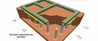
The design of a pile-strip foundation consists of a number of piles installed along the central axis of the strip with a certain pitch. The reinforcement frame of the piles is rigidly connected to the reinforced belt of the tape , combining these elements into a single mechanical system.
Excavation work includes creating wells and digging trenches , carried out simultaneously or in several stages. The construction of the belt is carried out according to the general rules, with the exception of the presence of additional reinforcement cage elements.
All work consists of two conditional stages:
- Creation of a pile system.
- Filling and holding the tape.
It is not always possible to combine or perform both points at the same time, although when pouring all the elements of the supporting structure at once, it is possible to achieve maximum strength and solidity of the base .
Laying depth
In this case, the depth of placement has a double meaning, since the piles and tape are immersed at different levels.
The depth of immersion of piles depends on the properties of the soil and is determined by the level of occurrence of dense layers.
The tape is immersed to a relatively shallow depth - about 30-40 cm , which, taking into account the thickness of the backfill layer, determines the depth of the trench at 50-70 cm.
The numbers are given conditionally ; these are the average values that occur most often.
To carry out the work, it is necessary to attract competent specialists who will inspect the site, calculate the parameters of the foundation and give accurate values for the immersion level of all elements.
An example of calculating the required number of supports
For simplicity, we will take the total weight of the house with all loads to be equal to 30 tons. This approximately corresponds to the weight of a one-story timber house 6:4 m, located in the middle zone with a snow load of up to 180 kg/m2 .
The bearing capacity of one pile is determined. The area of the support (blade) with a diameter of 0.3 m will be 0.7 m2. (700 cm2). The bearing capacity of the soil is usually taken to be equal to the arithmetic mean of the values of all layers found on the site. Let's say it is expressed in 3-4 kg/cm2. Then each pile will be able to carry 2.1-2.8 tons.
It turns out that for a house of 30 tons you need to use 11-15 piles . Remembering the need to have a safety margin, we accept the maximum value. The placement scheme can be taken as a pile field of 3 rows of 5 piles each.
The immersion depth and, accordingly, the length of the piles are taken equal to the depth of dense soil layers.
It is determined practically by the method of test driving a pile or drilling a well.
Step-by-step instructions for installing MZLF
Scheme of work for the construction of the MZLF:
- Preparing the site, removing the top layer of soil, marking.
- Digging a trench.
- Installation of piles.
- Laying a sand cushion.
- Assembly and installation of formwork.
- Assembling the armored belt, connecting it to the piles.
- Concrete pouring, curing.
- The final procedures are insulation, waterproofing, pouring the blind area, etc.
The diagram is shown for a foundation with driven piles; for other types, appropriate amendments are made.
Marking and driving piles
The marking of the pile field is carried out after preparing the trench. The first installation points are located in the corners, the rest are placed according to the design data evenly along the sides of the perimeter . After marking is completed, the piles are immersed to the required depth.
For this purpose, special equipment (construction piledriver) is used, which creates strong vibration. If there are other buildings in the immediate vicinity, diving is dangerous , since ground movements can cause sudden subsidence of houses.
Harness
Tying piles includes several operations:
- Trimming the tops to create an even horizontal field. If necessary, some piles are built up.
- At the top points the piles are connected by metal beams.
- The beams are connected to the reinforcement frame of the tape.
IMPORTANT!
Depending on the type of piles, the procedure may differ slightly from the above. For example, bored piles are simply connected to tape and reinforcement cage, and poured concrete into a single monolith.
Installation of formwork
The formwork is assembled as close to the trench as possible so that heavy panels do not have to be moved over long distances. The material for formwork is usually 25-40 mm edged boards . The higher and wider the tape, the thicker the boards.
The width of the boards is slightly greater than the height of the fill . The assembly must be done as tightly as possible, without gaps. The strength of the formwork ensures that there are no concrete leaks, so you need to pay close attention to it.
From the outside, the formwork is reinforced with vertical and inclined stops; from the inside, the position of the boards is fixed by transverse struts.
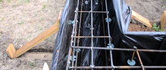
Foundation reinforcement
Reinforcement allows you to increase the tensile strength of concrete structures. A reinforcing frame is created with the calculation that the working (horizontal) rods are located under the surface of the concrete at a distance of 2-5 cm.
To do this, it is necessary to make a spatial lattice consisting of working ribbed rods 10-12 mm thick and smooth auxiliary rods installed in the form of clamps. Vertical reinforcement is needed only until the moment of pouring; afterwards it simply remains in the concrete mass .
Knitting reinforcement
The connection of reinforcing bars is made using the knitting method. Soft steel wire is used.
Knitting process:
- The wire is cut into pieces of 25-30 cm .
- A piece of wire is bent in half and placed under the connection point of the rods .
- The ends of the wire are raised up, clasping the crosshairs of the rods .
- A special hook is inserted into the loop and rotated around the other end. Usually make 4-6 turns .
The procedure is simple, skills appear almost immediately, even in people who have never knitted reinforcement before. The connection is tight and quite strong.
Pouring concrete
Concrete is poured as quickly as possible, in one go. Breaks of more than a day are unacceptable , as the concrete will begin to set, making further pouring impossible.
You will have to wait until the material has completely dried , and then continue work, but the connection will not be as strong as a monolith. Concrete should be poured at different points, evenly distributed along the length of the tape.
To do this, it is necessary to foresee the approach routes in advance and make a flexible tray that allows you to direct the flow of concrete to the right places.
After pouring, the material must be freed from air bubbles , for which a construction vibrator or continuous bayonet is used.
Final stages of work
The filled tape is covered with polyethylene to protect it from rain or scorching rays of the sun. To equalize humidity and relieve stress, the first three days the tape is watered with water every 4 hours , and then for 7 days watering is done three times a day.
The formwork is usually removed 10 days after pouring, and complete drying of the material is achieved after 28 days.
Exposure must be carried out in strict accordance with technology requirements . No retreats or initiative should be allowed, since the strength of the foundation is too important and does not allow liberties.
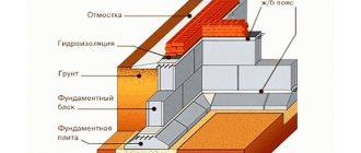
Waterproofing and insulation
After the concrete has hardened, the tape is waterproofed and, if necessary, insulated.
Waterproofing is applied to all surfaces, for which various materials are used:
- Hot tar.
- Bitumen mastic.
- Ruberoid.
- Impregnating compositions.
Manufacturers claim that the best option is to use impregnations. Builders adhere to proven methods and prefer applying bitumen mastic.
Insulating the foundation in conditions of excess moisture and heaving soils is a necessity.
The procedure consists of tightly installing a heat insulating tape on the surface of the tape (the best option is penoplex for the foundation).
Alternatively, you can use liquid polyurethane foam. It provides a completely sealed and waterproof insulating layer. Installation must be done both outside and inside the tape , which increases material consumption, but makes the insulation as effective as possible.
Pouring technology and installation work
- First you need to mark the base according to the previously made calculation.
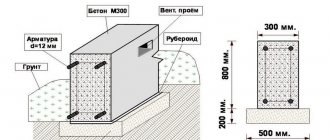
- Then trenches are dug to a depth of 40 cm. The width of the trench depends on the calculated area of the tape base.
- Wells are drilled in the corners and perimeter of the belt. The step between the piles is 2 meters. The depth of the well depends on the region in which construction is taking place. It should be 60 cm greater than the soil freezing depth.
The total depth of drilling a well includes the thickness of the sand cushion (30 cm), which must be done to protect the structure from mechanical stress. On average in Russia, the depth of the well is from 1.6 to 1.8 m. The diameter of the well will be equal to 1/3 of the width of the strip base.
- Then you need to waterproof the piles. To do this, a sheet of roofing felt rolled into a tube is pushed into each hole.
- The bottom of the strip base is covered with sand to a thickness of up to 30 cm and formwork is erected.
- It is not only the base tape that needs to be reinforced; each pile must have a reinforcing belt. Most often, 12 mm reinforcement is used for this. We recommend that you familiarize yourself in more detail with the reinforcement of strip foundation corners and the choice of reinforcement.
All reinforcing elements of the piles and base tapes are combined into a single structure, for which they are tied with wire or welded. You can familiarize yourself with the methods of tying reinforcement here.
- Pouring the foundation begins with wells for the piles. To eliminate the risk of voids in the concrete, every 20 cm of concrete mass must be thoroughly compacted.
The tape is poured a minimum time after the piles are poured. When pouring the foundation, you need to use construction vibration equipment, for example, a construction vibrator. Read about how you can make it yourself in our new publication.
- After 3 days, the formwork is removed and the foundation is waterproofed using roofing felt.