A beam is an element of building load-bearing structures that is widely used for the construction of interfloor floors. Floors, in turn, are designed to separate adjacent rooms by height, as well as to accept static and dynamic loads from interior items, equipment, people, etc. located on it.
In most cases, for private housing construction, wooden beams made of solid timber, hewn logs, laminated boards or veneer are used. These materials, with the correct selection of parameters, can provide the necessary strength and rigidity of the base, which is the key to the durability of the building.
We suggest you perform an online calculation of the floor beam for strength and bending , select its cross-section and determine the spacing between the beams. You will also receive a set of personal drawings and a 3D model for a better perception of the structure being built. The program takes into account SNiP II-25-80 (SP 64.13330.2011) and other reference sources.
Accurate and competent calculation of wooden beams in the KALK.PRO allows you to find out all the necessary parameters for the construction of a strong floor. All calculations are free, it is possible to save the calculated data in PDF format, plus diagrams and a 3D model are available.
- Beam length
- Determination of design load
- Maximum bending moment
- Required moment of resistance
- Moment of resistance of the floor beam
- Calculation of beam strength
- Calculation of beams for deflection (bending)
- Final beam parameters
Instructions for the calculator
Our service provides a choice of two types of calculations for single-span floor beams. In the first case, you are asked to calculate the section of the beam with a known step between them, in the second case, you can find out the recommended value of the step between the beams with the selected section characteristics. Let's look at how the calculator works using an example when your task is to find the cross-section of a beam.
To calculate, you will need to know a number of required initial parameters. First of all, these are the characteristics of the beam itself:
- section width (thickness), mm;
- beam span length (BLN in the image), m;
- type of wood (pine, spruce, larch...);
- wood class (1/K26, 2/K24, 3/K16);
- impregnation (yes, no).
If you do not know the thickness of the proposed beam , in the first block you should select the item “The ratio of the height of the section of the beam to its width is known - h/b” and specify the value 1.4. This is the most optimal value, which was obtained empirically and is indicated in many reference books.
Then you need to indicate the conditions under which the ceiling will be used:
- temperature conditions (< 35 °C .. > 50 °C);
- humidity conditions;
- there are constant increased loads or not.
After this, configure the design and fill in the fields of the calculator:
- length of the house wall on the inside, m;
- pitch between beams, cm;
- total length of the beam (BFL in the image), m;
- load on the beam, kg/m2;
- maximum deflection in fractions of the span.
If necessary, enter the cost of one cubic meter of wood in order to find out the total cost of all lumber.
Also, please note that usually the beam pitch is not made less than 0.3 m, since this is not practical from an economic point of view, and more than 1.2 m, since the subfloor may sag with all the ensuing consequences.
When you click the “ Calculate ” button, the service will calculate the beam online and display the recommended cross-section values for the selected beam.
In addition, in the “Calculation Results” block you can find out:
- beam parameters when calculating strength;
- beam parameters when calculating deflection;
- maximum beam deflection, see
A qualified calculation of the floor using wooden beams is the key to the durability of the structure and safety for your family.
Floor installation
In order for a building to last for a long time, beam floors must meet a high level of strength. Have good sound and heat insulation, as well as good ventilation.
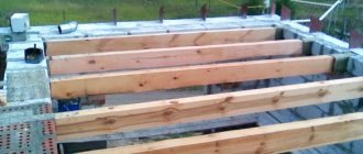
When installing wooden beams, the lighthouse installation method is most often used. First, the outer beams are installed, and then the intermediate ones. To avoid mistakes during work, use a level. In case of height differences, the beams can be leveled by placing cuttings soaked in bitumen primer under the end ends.
Before installation, the beams are spliced or cut to the required size. Splicing of timber beams along their length is usually carried out using the “key groove” method. To do this, the ends of the beams are cut down to 1/2 thickness and one end is buried into the thickness of the other. Then the joints are fixed.
Splicing two beams
The distance between wooden beams should not be less than 60 cm and exceed 1 meter. In a structure made of logs or laminated veneer lumber, the step is taken longer than in plank floors. When installing an attic floor, the distance between the chimney and the beams must be at least 40 centimeters.
To ensure the strength of the frame, the ends of the beams are recessed into the load-bearing wall by at least 15 cm. For I-beams, this value can be reduced to 7 cm. The recesses are sealed with mortar or foam. It is possible to secure the ends to the walls using steel ties. Waterproofing is done in the support areas on the beams.
Waterproofing of beams at support points is required
Calculation of floor beams
Independent calculation of a wooden floor beam is a long and tedious task that requires you to know the basics of engineering disciplines and strength of materials. Without certain skills and knowledge, manually selecting the material, calculating the required section or pitch of the beam is not only difficult, but sometimes impossible. However, we will try to tell you about the main characteristics that are needed for calculations and what algorithm our calculator uses.
Types of beams
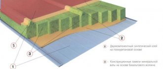
Currently, wooden beams used for the manufacture of floors can be divided into two fundamentally different types:
- solid;
- glued
Based on the name, it becomes clear that in the first case, it will be a solid piece of wood of a certain type of section (most often it is a beam with 2 or 4 edges), in the second case, it will be a laminated beam made of boards or LVL veneer.
Despite the low cost, for a number of objective reasons, wooden beams made of solid wood have recently been used less and less . The quality characteristics of this material are significantly inferior to laminated wood: the low modulus of elasticity contributes to the appearance of large deflections in the middle of the span (this becomes especially noticeable when the distance between the load-bearing walls is more than 4 meters), when drying, longitudinal cracks appear on the beams, which lead to a decrease in the moment of inertia of the deflection, Lack of impregnation exposes the wood to pests and rot.
Thanks to modern technologies, glued beams do not have such disadvantages . Their structure is homogeneous and the fibers are oriented in all directions - the overall strength and elastic modulus of the material increases, it receives protection from cracking, and special impregnation provides an increased level of fire safety and moisture resistance. These beams are allowed to be used for openings of 6-9 m and can be considered as a full-fledged analogue of an iron floor.
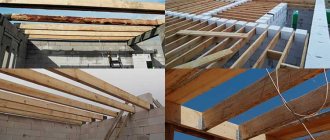
Solid wood beam
Glued beam from boards
Glued veneer beam
Cut log
Selection of beam section
In order to select the section of a beam yourself manually, you need to have a huge amount of knowledge in the field of strength materials, because you will need to apply in practice a large number of formulas and coefficients, so for a novice master this is a rather difficult and not entirely irrational task. Our calculator should help you make an approximate calculation of a wooden floor and save a significant amount of time. However, the user must understand that no program can replace a real specialist, since the operating principle of the service is based on processing standard tabular values and cannot take into account specific situations.
Calculating wooden floor beams is much easier using our calculator. You don't need to keep a lot of formulas in your head and worry about unproduced errors!
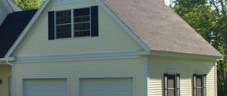
Features of floors
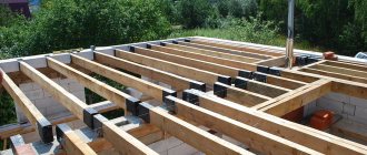
The photo shows the installation of floors.
Based on the experience of professional and independent developers, we can say with confidence that it is the wooden structures of interfloor slabs that are the most popular and often manufactured in the construction of private houses. (see also the article Cottages made of timber, advantages and disadvantages of the material)
This is due to several factors, of which the main ones can be identified:
- ease of installation (2 people are enough to manufacture them, and there is no need for specialized equipment, such as in the manufacture of reinforced concrete structures);
- low cost compared to all other types of structures;
- sufficient strength, reliability and durability;
- ease of repair and dismantling.
For more information about timber floors, watch the video in this article.
Beam Calculation - Example
The program algorithm for calculating beams is based on SP 64.13330.2011 (Updated edition of SNiP II-25-80). For greater clarity, we will analyze the calculation of a single-span beam for deflection and strength in an example, briefly describing the main stages of calculation and formulas.
Beam length
The estimated length of the beam is determined by the span length and the margin for laying them on the wall.
Finding out the length between spans is not difficult - use a tape measure to measure the distance that needs to be covered with beams, and to the resulting number add the amount of embedding in the “sockets” equal to 300 mm (150 mm per side) or more.
In the case when you are going to attach the beams to special metal fasteners, the span length will be equal to the length of the beam.
If your room has an irregular shape, for example, 4x5 m, it would be more correct to use beams of shorter length, i.e. 4 m, not 5 m.
Determination of design load
In order to correctly calculate the load on a wooden beam, you need to determine all types of influences on the floor.
The magnitude of the load can be found out in two ways: use SNiP 2.01.07-85 * Loads and impacts and use it to calculate all the necessary coefficients manually and then add them, or you can take regulatory data from reference books. If you make all the calculations correctly, then the first option will be more accurate, but no one is safe that a mistake will be made when performing long, cumbersome calculations.
Therefore, to obtain an approximate calculation, it is more advisable to take standard values and apply them in subsequent formulas. According to reference books, for interfloor ceilings the design load is usually 400 kg/m2, and for attics - 200 kg/m2.
Typical loads for interfloor ceilings - 400 kg/m2 and attics - 200 kg/m2 are not applicable in all situations . If it is expected that the base will be subject to an abnormally large weight, for example from heavy equipment, it is necessary to adjust the initial parameters.
Maximum bending moment
Bending moment is the moment of external forces relative to the neutral axis of the section of a beam or other solid body, in other words, in simple words, it is the product of force by the arm.
The maximum bending moment, accordingly, takes the greatest value that a given body can withstand without violating its integrity.
If a uniformly distributed load acts on the beam (this is the case implemented in the calculator), then the value of the maximum bending moment will be equal to:
Bending moment (formula): Mmax = q × l2 / 8
- q is the magnitude of the load on the floor;
- l is the size of the floor span.
Required moment of resistance
The moment of resistance is the ability of a material to resist bending, tension or compression. In order to determine this value for a wooden beam, you need to use the ready-made formula:
Required moment of resistance (formula): Wreq = Mmax / R
- Mmax – the value of the maximum bending moment;
- R is the value of the design resistance of wood.
Separately, we need to talk about the value of R. It has a number of correction factors that need to be taken into account when calculating the beam if you want to get the most accurate result. The full formula looks like this:
Design resistance of wood (formula): R = Ri × mп × mд × mт × ma × γсc × …
- Ri is the calculated bending resistance of wood, selected depending on the calculated values for pine, spruce and larch at a humidity of 12% according to SP 64.13330.2011;
- mp – transition coefficient for other types of wood;
- mд – correction factor adopted in the case when permanent and temporary long-term loads exceed 80% of the total voltage of all loads;
- mt – temperature coefficient;
- ma – coefficient adopted in the case when the tree is impregnated with fire retardants;
- γсc – wood service life coefficient.
- ... - there are other less important coefficients, but they are practically not used in calculations, since the magnitude of the correction is too insignificant.
It turns out that, in essence, the value of R is the product of the calculated bending resistance of wood and various corrections. In most cases, to obtain an approximate result, these corrections are not taken into account, and the value of R is taken equal to Ri.
Moment of resistance of the floor beam
Depending on the cross-sectional shape of the beam (square, rectangle, circle, oval...), the formulas for finding the actual moment of resistance will differ . Our calculators use only two types of profile: rectangular and hewn log. We will continue to analyze the algorithm using the example of a rectangular section:
Moment of resistance of the beam (formula): W = b × h2 /6
- b – beam width;
- h – beam height.
Self-production of laminated wood beams
One solution for spanning long spans is to use wooden beams in the floors. Let's consider a span of 6 meters - which beams can withstand a larger load.
According to the type of cross section, a long beam can be:
- rectangular;
- I-beam;
- box-shaped
There is no consensus among self-builders as to which section is better. If we do not take into account purchased products (factory-made I-beams), then the ease of production in “field conditions”, without the use of expensive equipment and accessories, comes first.
Just Grandfather FORUMHOUSE User
If you look at a cross section of any metal I-beam, you can see that from 85% to 90% of the metal mass is concentrated in the “shelves”. The connecting wall contains no more than 10-15% of the metal. This is done based on calculation.
Which board to use for beams
According to the strength of strength: the larger the cross-section of the “shelves” and the farther they are spaced apart in height, the greater the loads the I-beam will withstand. For a self-builder, the optimal I-beam manufacturing technology is a simple box-shaped structure, where the upper and lower “shelves” are made of boards laid flat. (50x150mm, and the side walls are made of plywood with a thickness of 8-12 mm and a height of 350 to 400 mm (determined by calculation), etc.).
Plywood is nailed to the shelves or screwed with self-tapping screws (not black ones, they do not work for cutting) and must be set with glue
.
If you install such an I-beam on a six-meter span with a step of 60 cm, then it will withstand a large load. Additionally, an I-beam for a 6-meter ceiling can be lined with insulation.
Also, using a similar principle, you can connect two long boards, collecting them in a “package”, and then put them on top of each other on an edge (take boards 150x50 or 200x50), as a result, the cross-section of the beam will be 300x100 or 400x100 mm. The boards are placed on glue and tied together with pins or placed on wood grouse/dowels. You can also screw or nail plywood to the side surfaces of such a beam, having previously lubricated it with glue.
Also interesting is the experience of a forum member under the nickname Taras174,
who decided to independently make a glued I-beam to span a span of 8 meters.
To do this, the forum member purchased 12 mm thick OSB sheets and cut them lengthwise into five equal parts. Then I bought a board 150x50 mm, 8 meters long. Using a dovetail cutter, I used a dovetail cutter to select a groove 12 mm deep and 14 mm wide in the middle of the board, so as to create a trapezoid with a downward expansion. OSB in grooves Taras174
glued it in using polyester resin (epoxy), having previously “shot” a strip of fiberglass 5 mm wide to the end of the slab with a stapler. This, according to the forum member, would strengthen the structure. To speed up drying, the glued area was heated with a heater.
Taras174 FORUMHOUSE user
On the first beam I practiced “pushing my hand.” The second one was done in 1 working day. In terms of cost, taking into account all materials, I include a solid board of 8 meters, the cost of the beam is 2000 rubles. for 1 piece
Despite the positive experience, such “squatter construction” did not escape several critical remarks expressed by our experts. Namely.
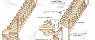
The main condition for any construction is simplicity and reliability of the structure, but in order to achieve this, correct calculations of the strength of the material must be made. Since a wooden frame is used to build wooden houses, an attic or an attic, its choice must be approached with all responsibility, because the durability, reliability and stability will directly depend on the load the timber can withstand (100x100, 50x50, 150x150, etc.) built house.
To correctly calculate the load that a beam can withstand, you can use special programs or formulas, but in this case, additional loads that directly affect the strength of the structure will have to be included in the calculations. In order to correctly calculate the load on the beam, you will have to indicate the snow and wind influences present directly in the development region, as well as the characteristics of the materials used (thermal insulator, timber, etc.).
In this article we will look at what load a beam of size 50x50, 100x100, 150x150 will withstand in various structures, such as a log house, a wooden floor and a rafter system, and as an example we will analyze the latter, because this is the most important and complex work.
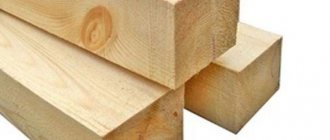
In the photo you can see varieties of timber, which differ not only in shape, but also in the load they can withstand.
What will we talk about:
Calculation of beam strength
In order to determine whether a beam is suitable for strength or not, it is necessary that the moment of resistance of the floor beam (W) is equal to or greater than the required moment (Wreq):
Wreq ≤ W
But we cannot calculate the real moment of resistance of the floor beam, since its height is not known. In this case, you need to either use an enumeration of sections, based on the condition that the most optimal height to width ratio is 1.4:1, or simply accept W = Wrequired, due to the fact that we do not violate the conditions of the given formula. Also, after these manipulations, the parameter h will become known.
The KALK.PRO online calculator for calculating beam strength will quickly calculate the required section so that the floor can withstand the design load FAST and FREE.
Advantages and calculation of beam floors
The entire structure consists of beams and boards, which are called rough. The beams themselves can be load-bearing, located simply next to each other, or fixed in a special way, which is much more reliable. The standard sizes of beams are 20-40 centimeters in height and 15 meters long, plus 8-20 centimeters in width.
Unlike reinforced concrete attic floors, wooden ones are installed dry. It is much lighter in weight, so in private construction it is better to use just such an overlap. On the other hand, wooden floors are the least soundproofed, so you will have to spend money on additional measures.
The beams are located at a distance of 60 centimeters to 1.5 meters. Of course, the more often you install them, the greater the load the attic will be able to withstand in the future, but the foundation of the house will also have to endure a greater load.
Light partitions are usually mounted on a wooden attic floor - most often frame ones, to which the attic rafters are directly attached. They need to be installed perpendicular to the beams or edgewise.
But if for some reason the internal walls of the attic have to be placed parallel to the ribs or beams, which is not at all according to the rules, then the structures in these places must be strengthened. Most often, fragments of boards are used as such elements, which are attached perpendicular to the ribs of the floor.
And this graph will help you calculate the required number of beams and the load on them:
Calculation of beams for deflection (bending)
The method for determining beam deflection is much simpler. With a distributed load, the formula applies:
Beam deflection (formula): f = (5 × q × l4) / (384 × E × I)
- q is the magnitude of the load on the floor;
- l is the size of the floor span;
- E – elastic modulus;
- I – moment of inertia.
We know the first two parameters; the modulus of elasticity for wood is usually taken to be 100,000 kgf/m², although this is not always the case, and the moment of inertia, depending on the shape of the section, is calculated using different formulas. For a rectangle:
Moment of inertia (formula): I = b × h3 /12
- b – beam width;
- h – beam height.
Putting everything together, we get the final formula for calculating the deflection of a beam:
Beam deflection (final formula): f = (5 × q × l4) / (384 × E × (b × h3 / 12))
After you receive the desired value, you need to compare it with the value of the permissible (maximum) deflection of the beam in fractions of the span. This parameter is set by SNiP II-25-80 “Wooden structures”:
| Structural elements | Maximum beam deflection, no more |
| 1. Beams between floors | L/250 |
| 2. Attic floor beams | L/200 |
| 3. Floors with screed/plaster | L/350 |
For example, for interfloor ceilings with a span length of 400 cm, we get the condition - 400/250, i.e. the maximum possible bend in this situation is 1.6 cm.
If your f value exceeds it, you need to change the beam section upward until it becomes less than the maximum deflection.
Our wooden beam deflection calculator will automatically select the necessary section parameters and save you from complex cumbersome calculations.
Final beam parameters
After you select the section when calculating strength and deflection/bending, you can determine the minimum permissible parameters of the beam.
Let's assume that when calculating strength you received a cross-section of 165x150 mm, and when calculating deflection - 239x150 mm. Obviously, in such a situation, you should choose the largest value , that is, the deflection value, because if you do exactly the opposite, the ceiling will withstand the load, but will be very deformed and there can be no question of any even ceiling.
As a result of calculating the load-bearing capacity of a wooden beam, we use a section equal to 239x150 mm, but here we are faced with another problem - no one produces beams of this size in series. In this case, it is necessary to round up, usually in multiples of 50 mm, i.e. A beam of 250x150 mm is suitable for us. In some situations, you can refer to GOST 24454-06, which lists all standard sizes of materials.
Calculating beams online without knowing the strength of materials is one of the main advantages of the KALK.PRO service.
Flooring with boards 200 by 50 and other common sizes
These are the types of beams on a span of 4 meters that are allowed by the standards.
Most often, in the construction of wooden floors, boards and timber of the so-called running sizes are used: 50x150, 50x200, 100x150, etc. Such beams meet the standards ( after calculation ) if it is planned to cover an opening of no more than four meters.
For floors 6 or more meters long, the dimensions 50x150, 50x200, 100x150 are no longer suitable.
Wooden beam over 6 meters : subtleties
A beam for a span of 6 meters or more should not be made of timber and boards of standard sizes.
You should remember the rule: the strength and rigidity of the floor depend to a greater extent on the height of the beam and to a lesser extent on its width.
A distributed and concentrated load acts on the floor beam. Therefore, wooden beams for large spans are not designed “end-to-end”, but with a margin of strength and permissible deflection. This ensures normal and safe operation of the ceiling.
50x200 - overlap for an opening of 4 and 5 meters.
To calculate the load that the ceiling will withstand, you must have the appropriate knowledge. In order not to delve into the strength of strength formulas (and when building a garage this is definitely redundant), an ordinary developer just needs to use online calculators for calculating wooden single-span beams.
Leo060147FORUMHOUSE user
A self-builder is most often not a professional designer. All he wants to know is what beams need to be mounted in the ceiling so that it meets the basic requirements for strength and reliability. This is what online calculators allow you to calculate.
These calculators are easy to use. To make calculations of the required values, it is enough to enter the dimensions of the logs and the length of the span that they must cover.
Also, to simplify the task, you can use ready-made tables presented by the guru of our forum with the nickname Roracotta.
RoracottaFORUMHOUSE user
I spent several evenings to make tables that would be understandable even to a novice builder:
Table 1. It presents data that meets the minimum load requirements for the floors of the second floor - 147 kg/sq.m.
Note: since the tables are based on American standards, and the sizes of lumber overseas are somewhat different from the sections accepted in our country, you need to use the column highlighted in yellow in the calculations.
Table 2. Here is data on the average load for the floors of the first and second floors - 293 kg/sq.m.
Table 3. Here is the data for the calculated increased load of 365 kg/sq.m.