What it is?
Sheet piling is a solid wall made up of identical elements connected to each other.
The connection of individual tongues allows the structure to withstand heavy loads and remain a reliable reinforcement for the walls of the pit.
Increased strength and stability allow the use of sheet piling on weak soils:
- sandy,
- marshy,
- with high groundwater levels.
Some types of sheet piles are used to strengthen the coastline. They are widely used for wide pits with a depth of more than five meters.
Types of tongue and groove elements
Originally, sheet piling walls were made from logs or wooden plates. Such sheet piling fencing is still widely used in land reclamation, landscaping and other types of work that are not associated with high complexity and requirements. This material is distinguished by its low cost and availability. Its turnover and durability are naturally low.
This is what profiles for installing sheet piling walls look like
However, Larsen metal tongue and groove has a high weight and significant cost. It is not always possible to preserve elements without trimming or deformation.
At the same time, expensive products are turned into scrap metal after use. Sheet piles made of polymers - polyvinyl chloride and composite - are being introduced into construction practice. In addition to their low weight, these products have a lower coefficient of surface friction, which makes them easier to insert and remove.
An example of a Larsen tongue and groove made from polymers
Building regulations
SP 45.13330.2017 regulates the arrangement of earthen structures . In accordance with the requirements of the document, when installing sheet piling fencing, as well as other construction work, it is necessary to take into account intersections with existing communications. Particular attention should be paid to communication lines, power cables and main pipelines.
SNiP 12-04-2002 “Occupational Safety in Construction” does not require the use of any specific methods for strengthening the steep walls of pits and trenches, but prohibits work in such excavations without additional strengthening of the walls if their depth exceeds:
- 1 meter, when working on sandy soil;
- 1.25 meters, when building in sandy loam;
- 1.5 meters for clays and loams;
- no more than 2 meters for dense soils.
Also, the arrangement of fencing structures is regulated using GOST R 57365-2016 “Sheet piling walls. Rules for the production of work."
According to this document, it is recommended to carry out preliminary preparation of the construction site for the placement of sheet piling, mark individual piles, and also conduct engineering surveys to determine the need to use sheet piling.
How to install sheet piling for a pit
The construction of an artificial wall is carried out in strict accordance with the developed design documentation and drawings. The design specifies the depth of the fence, height, diameter, type of tongue and groove and fixation.
Before work, a hydraulic analysis of the soil is carried out and a technological map is drawn up.
The installation procedure is as follows:
- Deliver materials and tools to the construction site.
- Using a crane, the sheet piles are distributed around the perimeter of the object.
- Mark the installation site for each pile.
- Slinging is being carried out. The elements are delivered to the marked installation area.
- The head of the loader is attached to the tongue.
- The pile is aligned strictly vertically. Gradually immerse it in the ground.
- The spacers are removed. The pile is lowered to the required depth.
The installation of elements is carried out until a sealed fence is obtained around the perimeter of the pit.
SNiP 3.02.01-87
Fences erected using the sheet piling method are regulated by the standards described in the technological map.
Here are the following:
- Fundamentals of fire and environmental safety.
- Indicators of quality work performance.
- Requirements for sizes, types of raw materials used.
This is only a small part of the description. The standards are taken into account by engineers, foremen and other people who are responsible for the technical side of construction.
The quality of construction is assessed by SNiP. A complete list of requirements for the installation of such fences is given here:
https://docs.cntd.ru/document/5200242.
Varieties
Several types of sheet piles are used to create pit fencing . Each type has its own characteristics and purpose; the type of tongue and groove can also limit the possibilities of using installation technologies.
Larsen tongue and groove
It is a metal profile of a special shape, called “trough-shaped”. The edges of the tongue and groove are equipped with locks, which make the fence a solid structure. Profile sizes can reach 35 meters in length. The width is 0.8 m and the thickness varies from 1.5 to 2.3 cm.
There are various models of this type of tongue and groove, which may differ in both size and shape. One of the models is L5:
- Strength – 800 kN/m.
- One linear meter of profile weighs 100 kg.
- The material used is St3 or 16ХG.
Typically, Larsen sheet piles are installed using vibrating equipment. Scope of application: complex and highly complex objects. It performs well on loose soils, swampy soil, and protects pits from groundwater.
The disadvantages of the product include its high cost and the fact that installation requires higher installation accuracy than when working with other types of tongues.
All modern steel tongues are various analogues of the Larsen tongue. They may differ from it in the shape and design of the locks, which improve the strength characteristics and also simplify the driving of piles.
In terms of their functional purpose and properties, steel sheet piles of other configurations are completely identical to the Larsen sheet pile.
Metal tubular welded
A special type of metal steel tongues is welded tubular . Due to their shape, they stand out among analogues and differ from Larsen tongue and grooves in their several times increased resistance to loads. Another advantage is long service life. The disadvantages include the high cost of mounting the device from steel pipes.
Wooden
Tongues made of wood are the oldest type. It is allowed to make fences from logs, boards, timber. The elements are immersed in the soil to a depth of 6 meters, mounted in one or two rows, close to each other.
When arranging a fence from specially treated timber, each element has a protrusion and a groove, which allows you to connect the structural elements together.
Main advantages:
- availability of material,
- its relatively low price,
- Possibility of installation without the use of special equipment.
Negative qualities include the complexity of installation, low strength and resistance to environmental influences in comparison with metal and plastic tongues.
Polymer
As an alternative to metal tongues, elements made of polymer materials can be used. The most popular are PVC fencing .
They have increased resistance to corrosion and are resistant to mechanical stress. PVC panels are lightweight, making their installation easier, which reduces installation time.
This type of sheet piles is mainly installed in places where there is increased exposure to aggressive environments, primarily near bodies of water, to strengthen the coastline, for arranging facilities near salty sea water and in other similar cases. Installation method: pressing or vibration. Not used for driving immersion.
Reinforced concrete
Made from reinforced concrete . There are grooves along the edges that allow you to connect adjacent tongues in the fence. Maximum length – 16 meters. They are distinguished by their heavy weight, as well as their tendency to cracking and loss of integrity due to mechanical damage.
There is no possibility of dismantling; after construction, the buildings become the outer perimeter of the foundation. They are used in the construction of hydraulic structures.
What is a pick-up from boards for a pit?
On water-saturated unstable soils, sheet piles are installed as a continuous wall. The profile piles are rotated 180 degrees relative to each other and connected with locks. In plan, the structure resembles a sinusoid - in this form, the stability of the wall is maximum. The pipe piles are not unfolded, but they are also installed closely.
On dense soil, in which stability is higher and the pressure on the wall is correspondingly lower, sheet piles can be placed not closely, but at intervals. The gaps are covered with boards, steel sheets, etc. This is the rebate. It allows you to save money (fewer tongues will be needed). Subsequently, the backfill is used as formwork when pouring the foundation.
If the soil is dense but saturated with water, this measure is not enough: the intake is permeable. In this case, water reduction measures are necessary, that is, additional costs. Calculation will show which will be more economical in your case.
We not only do sheet piling, but also design fencing. If necessary, we conduct soil tests. If you contact us, we will together with you choose the option that is suitable in terms of hydrogeological conditions and the most economical in cost.
We know everything about sheet piling
Work experience - 10 years. More than 270 completed projects. Not a single negative review. For any questions call: 8 800 707-72-09
Used tongue-and-groove technologies
The main types of sheet piling methods , which can be used individually or combined in various combinations:
- impact method;
- vibration method;
- indentation
A variety of machines are used for work. Each technology places special demands on technology. The most common installations are:
- Low-frequency vibrating machines (9-10 Hz, force up to 1700 kN).
- Mid-frequency (10-30 Hz, force 270 kN).
- High-frequency units with the ability to adjust imbalance.
- High frequency vibrators with imbalance adjustment and non-resonant on-off phases.
- Pressing systems.
- Mechanical hammers.
- Air hammers.
- Hydraulic hammers.
- Diesel hammers.
Vibration methods are the most effective, and the use of a pile driver allows vibrators to achieve excellent accuracy when installing sheet piles to a given depth.
Vibrator
The vibration driving technique improves the accuracy of pile installation and reduces their tendency to warp. Construction machines with a mounted vibrating head are used for work.
Before starting work, it is connected to a tongue and groove. Due to the frequency vibrations caused by the equipment, the density of the soil decreases, and the pile gradually penetrates into the ground, going to the required depth.
Main parts of the unit:
- vibration exciter with two or four electric motors;
- dynamic impact absorber;
- hydraulic head.
Although the operation of vibrating machines has less impact on the surrounding space than the action of driving pile units, vibration can also have a negative effect on surrounding structures. Transmitted through the ground, it is well received by the foundations of buildings and is transmitted to supporting structures, which can lead to their destruction.
To reduce the effect caused by vibrations, high-frequency installations are used ; their negative impact on nearby buildings is significantly less.
Driving with a hydraulic hammer
Vibration methods do not work well if it is necessary to install sheet piling in dense sand, gravel, if they are located above groundwater, as well as in cohesive soil. In this case, impact methods for installing piles are more effective.
For work, a hydraulic hammer can be used, which is a vertically mounted rod with a striker. The striker moves along the rod and hits the tongue, driving it into the ground.
This is the simplest and cheapest method of installing sheet piling , however, this technique is not applicable in densely populated areas, near historical and architectural monuments.
Impact loads are transmitted through the soil to surrounding structures, which lead to a decrease in the strength of foundations and load-bearing structures and can cause deformation of structures.
Drilling with leader drilling
To make it easier to install piles and to make work go faster, leader drilling technology is used.
For this, an auger drill is used , which locally loosens the earth, creating a well with low soil density. The drilling process is carried out using special units - mobile drilling rigs.
This method is successfully used when working on frozen and dense soils, where the need for its use is obvious. Lead drilling is in demand during construction on low-density soils - here this is due to the impossibility of using vibration and impact immersion methods due to the high risk of pit walls collapsing.
In places with high groundwater levels, preliminary drilling helps ensure the accuracy of pile installation by pre-setting the trajectory of its immersion.
Screwing and pressing, static pressing
Vibration and noise impacts caused by driving and vibration immersion can spread far and have a negative impact on the surrounding area.
If there are building structures nearby that are sensitive to these types of impacts, they will be damaged. The impact is especially noticeable if buildings are located on sandy, loose soils .
When vibrating, water-saturated sand tends to become compacted, which means the soil will sag, which will lead to the destruction of the foundation of nearby structures.
In this case, it is safer to use the methods of screwing or pressing the tongue. Well suited for clays, loams, sandy soils, and other low-density soils.
The main advantages of the method:
- No shock or vibration impacts on nearby buildings.
- Low noise level during operation.
- The likelihood of damage to the pile is reduced, as, for example, with the driving installation method.
The disadvantages include the large weight and size of the equipment, which makes it difficult to prepare it for work and transport it. All elements of the unit are transported by several trucks, which affects the cost of construction, so this method is used exclusively for the construction of large objects or the construction of large buildings.
Submersion dive
In difficult cases, when the passage of soil is difficult, auxiliary methods, such as explosive drilling or undermining, can be used.
Immersion with undercutting, when water flows under high pressure, is an effective method for installing sheet piles in high-density soils .
The technique involves introducing a small amount of water or a special solution through nozzles located near the base of the pile.
Low fluid consumption makes it possible to well control the degree of soil erosion . Therefore, the negative impact occurs only in a small area, along the movement of the sheet pile, and has a slight effect on the strength of the soil.
When working on dense soil, low pressure water is used. In this case, water has a slight effect on the properties of the soil and does not lead to its subsidence.
Flushing here, as a rule, is used as an auxiliary function during vibration driving of piles. Flushing is especially effective in combination with high vibration exposure .
Fencing installation technology
Installation of pipes in wells can be done in different ways, but in any of them, the first stage will be drilling literal wells .
The most common drilling methods are auger and ball . In these types, the walls of the wells are fixed using a clay solution under a certain level of pressure. Greater density of the pipe will be ensured thanks to clay. The price for this type of work will depend on the depth to which the pipes will be lowered, the quality of the soil and labor intensity. The quality of installation directly depends on the method of immersing the tongues.
There are the following methods for driving sheet piles:
- The sheet pile is driven in using pile drivers. For example, a pendulum pile driver. But it is not used in the city due to the dense arrangement of buildings.
- The sheet piles are immersed in pre-drilled holes.
- The tongue and groove is screwed and pressed. In this case, it is a steel pipe.
- The sheet pile is lowered into a pre-drilled hole, which is simultaneously filled with cement.
The video shows the process of vibrating the sheet piling into the ground:
Calculations
Sheet piling is made before starting work on creating a pit. The elements that will bear the main load are driven into the ground. At the initial stage, the system is in equilibrium and the soil presses on the sheet pile from both sides with equal force.
After the excavation has begun, the pressure on one side - on the inside of the pit - decreases as the amount of soil in this area decreases. The balance is disrupted, the soil from the outside begins to put pressure on the fence. Therefore, it is necessary to calculate the sheet pile in advance in order to understand what load it can withstand .
During the calculations, the required cross-sectional dimensions and the required immersion depth are determined. They must be such that the fence not only remains stable and maintains the balance of the soil, but also maintains a certain margin of safety.
Calculations can be made using one of two methods: graphic-analytical and analytical.
The sheet piling parameters are determined from the condition Mu≤(m/yn)Mz , where:
- Mu is the moment caused by the force of soil pressure on the sheet piling and contributing to its overturning;
- Mz is the moment of resistance to overturning, which works due to the pinching of the sheet piling in the ground;
- m – coefficient characterizing the operating conditions of the sheet pile in the ground; for soft soils the value is taken equal to 0.7;
- yn is a reliability indicator; for dry soil it is taken equal to 1.1, for the case of high groundwater – 1.2.
To determine the moment of resistance to overturning, it is necessary to calculate the load-bearing capacity of the sheet piling according to the general formula for calculating the load-bearing capacity of piles F= yc(ycrR·d + V·∑ ycri·fi·li) , where:
yc – coefficient characterizing the work of the pile in the ground;- ycr – coefficient that determines the resistance of the soil under the sheet pile;
- R – soil resistance under the sheet pile;
- d – diameter of the supporting sole;
- V is the perimeter of the sheet pile section;
- ycri – coefficient characterizing the work of soil on the side surfaces of the sheet pile;
- fi – soil resistance on the side surfaces of the sheet pile;
- li is the length of the side faces of the tongue.
The coefficient values are taken from the relevant regulatory documents and are determined separately for each type of tongue and groove. The final calculations are carried out by drawing up diagrams and selecting the driving depth in such a way that condition (1) is satisfied. During the calculations, it is also necessary to additionally check the wall, beams and spacers for strength, and the tongue itself for rupture of the lock.
How to calculate a fence
To prevent deformation of the walls of the enclosing structure after digging up the soil, it is necessary to carry out several calculations. They are based on the following characteristics:
- Type of fencing.
- Material installation depth.
- Sheet pile dimensions.
- Interaction forces.
Using mathematical calculations of sheet piling, you can determine the required diameter of the sheet pile at the point of driving below the base and in the selection of the spacer system. Builders use proven formulas or online calculators that allow them to get accurate results in a few seconds.
The calculation formula is as follows: M1 ≤ m/γ * M2, where:
- M1 indicates rollover resistance.
- M2 determines the holding torque.
- m indicates the operating conditions coefficient.
- y is a symbol for the reliability coefficient.
Stages of work
Installation of tongue and groove can be done in several ways:
- driving,
- using low-frequency or high-frequency vibrations,
- pressing,
- screwing,
- by erosion method.
Technologies differ in the nature of the impact and are selected depending on the type of soil, as well as construction conditions. But the installation principles are basically similar and involve immersing, in one way or another, the pile into the soil.
Therefore, the general procedure remains the same, and the changes concern a few features of the use of a particular technology:
Site preparation, placement of special equipment, delivery of sheet piles;- The material is distributed along the perimeter of the pit. Then markings are made, the installation location of each element is determined, slinging is performed and each pile is delivered to the intended installation site;
- The tongue and groove are aligned strictly vertically, and the head of the loader is mounted;
- The pile is installed using the impact method, pressing or vibrating it into the soil. During the installation process, centering is carried out;
- If Larsen tongue and groove is used, then the grooves of each subsequent pile are inserted into the previous one, thus forming a lock. To minimize friction in the lock, lubricant is used.
When using Larsen tongue and groove repeatedly, the upper part of the profile may become deformed. It is recommended to cut it off to continue using the element.
After the installation of the sheet pile is completed, the depth of its immersion is monitored . The difference between the actual position of the elements and the design value should not exceed the maximum permissible deviations, otherwise the sheet pile will be removed and re-installed.
What is fencing a pit with sheet piles?
A sheet piling enclosing system is a monolithic wall that consists of sheet piles that compact the soil and localize the area where deformations or shifts can occur. Depending on their purpose, structures can be temporary or permanent. The second type performs the functions of permanent formwork for the foundations of buildings, plinths, walls and basements. It also creates a waterproof barrier to surface water.
There is no need to carry out excavation work to install a sheet piling wall. All components are first dug into the soil and fixed there. After this, the soil is brought to the surface.
The wall does not require a strip foundation and can be placed on any soil without taking into account the depth of freezing. It does not have much impact on the soil and is installed below the frost line. Sheet piles are held in place by soil friction rather than by the strength of the foundation.
Unlike traditional systems, sheet piling can withstand large displacement and bending loads, without the need for reinforced concrete supports.
When and why is it necessary
Strengthening the pit with tongue and groove is used for the following purposes:
- Strengthening the sides of the recesses under the foundations of the building.
- Protection of pit walls from crumbling.
- Localization of the construction site.
- Coastline maintenance.
- Arrangement of hydraulic structures.
- Strengthening foundations.
- Organization of sealed containers for industrial waste.
- Arrangement of treatment structures.
- Strengthening railway tracks.
In some cases, a sheet pile wall is erected at the zero stage of work in order to comply with the requirements of SNIP, when it is necessary to work below the zero soil level. When excavating vertically, such a fence provides enhanced protection of the walls from falls and landslides. Recesses with inclined walls are more likely to crumble, so they are strengthened first.
A distinctive feature of sheet piles is the possibility of reuse, therefore the choice of such systems is preferable to the organization of a water-absorbing system.
Strengthening
During construction work carried out on soft soils, there is a high probability of subsidence, deformation and even collapse of the sheet piling. Therefore, it needs to be further strengthened. Several effective technologies have been developed that increase the stability of sheet piles.
Installation of anchors
When arranging sheet piling, a method that is often used is to use special anchors to strengthen the structure . They are laid in soil located outside the zones of active interaction between soil and sheet piles. One such anchor can withstand loads of up to 500 kN.
Installation of reinforcing elements is carried out along the entire perimeter of the pit, the gaps between adjacent anchors are 1-3 meters. To maximize the effect, the elements are installed at an angle (from 30° to 60°).
Each anchor is a reinforced concrete structure buried in the ground. To lay it, a well is made, in which metal fittings and rods are then placed. The well is then filled with concrete. When the solution hardens, the rod is attached to the tongue, passing it through a hole specially made for this purpose and fixing it with fasteners.
To successfully implement this method, it is necessary to carry out all work carefully, with great precision , which requires a lot of labor and increases the financial costs of building the facility. Therefore, anchors are installed only in cases where the dimensions of the pit do not allow the use of spacer elements.
Spacer mounts
Spacers are installed if the distance between the opposite walls of the pit allows it. The maximum permissible distance depends on the type of soil and the type of spacer used.
Typically, metal pipes are used for this purpose , which are installed in several tiers at intervals of 4 to 6 meters. If the length of the spacers is large, then special racks made of I-beams or tongues are used.
This method of strengthening is characterized by increased metal consumption. To reduce this parameter, you can use inventory frames. In this case, inventory panels are placed on the fence tongues. If the dimensions of the pit are small and the soil is dense, then you can do without spacers by using cantilever fastening of the tongues.
Cantilever type fencing
If the pit depth is less than five meters, then it is permissible to use sheet piles fixed in the ground. The lower part of the element is immersed in the soil below the bottom of the excavation - you should make sure that it is securely pinched and does not have a tendency to collapse.
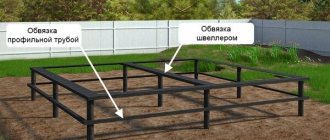
When installing sheet piles in soft soils, they are buried to more than two-thirds of the height of the pit. To increase the strength of the structure, a strapping frame made of beams of various sections is mounted on the top of the fence.
With this method of strengthening, it is necessary to prohibit the movement of heavy equipment near the pit. Also, construction materials should not be placed or stored near the fence.
Installation of sheet piling fencing for a pit
The construction of a tongue and groove fence depends on the materials used. Wooden products can only be used if the soil does not contain large stones, wood waste and other debris. The permissible pile driving depth cannot exceed 6 meters. Failure to comply with this requirement will result in the fence being ineffective or damaged. The tongues are immersed in the soil closely over their entire length. At this stage, any cracks and voids should be eliminated. If a double system is used, then a width of up to 1 m is maintained between the tongues.
When installing the structure on the bottom of a reservoir, the depth should not be less than 2 m. To minimize or prevent the likelihood of washing out the backfill, an outer row of sheet piles with increased density should be provided. When the pit depth is 3-5 m, the recesses between the walls are covered with a mixture that consists of 15% clay.
Steel sheet piles are only suitable for strong soils. They are driven to a depth of 7 m and are suitable for repeated use, subject to the operating rules. When tongue-and-groove piling with a hammer or vibratory hammer, the tightness of the products around the perimeter of the fence should be taken into account. In most cases, such systems are installed according to the principle that the surface water level becomes lower by 50 cm, and in relation to the aquifer - by 0.7 m.
Dismantling of steel products is quick and easy. To do this, use strapping belts placed around the perimeter of the trench and spacers in the corners.
The method of fastening the steel sheet pile is determined by the technology of soil development and the depth of the pit. To simplify the installation process, it is better to use cylinder piles rather than rectangular ones. They are made from sheet steel and are not equipped with cross braces.
Standards in the technological map and SNIP
The basic SNIP requirements for the installation of sheet piling structures are as follows:
- The equipment is selected taking into account the length of the components of the pile system. If it reaches 26 m, special marks should be provided for the tongues. The equipment is calculated using special computer calculators that use the theory of wave impact.
- Undermining the pit for easier fixation of sheet piles is permitted only in cases where the construction site is located far from residential buildings. The minimum distance between buildings should be 20 m. In this case, the immersion depth is doubled.
- Fencing pits is one of those types of work that are regulated by state standards and require documentation.
Common mistakes
Most often, when arranging the foundation pit, difficulties arise that are difficult to eliminate. Therefore, you should take care in advance to comply with the requirements of building codes and regulations:
- Sometimes, after installing a sheet pile, it is discovered that its immersion depth does not correspond to the design one. This leads to a decrease in the stability of the structure, which increases the risk of collapse of the pit walls. In this case, it is necessary to remove the tongue and reinstall it.
Gaps between adjacent fencing elements - there is no strong connection between the lock. This leads not only to deterioration of the waterproofing of the object, but also reduces the strength of the fence. The deficiency can be eliminated by reinstalling the fencing elements.- As a rule, the sheet pile penetrates into the soil several meters deeper than the level where the bottom of the pit is constructed.
This poses a danger if there are communications or structures under the pit that are unknown to the builders. If the surveys were not carried out well enough before the start of work, this could lead to a serious accident, which could result in significant financial losses.
The need to correct errors can significantly increase construction costs, which means each stage of the work must be carefully prepared. You should also take a responsible approach to performing all technological operations of installing sheet piling for the pit.
Formula and calculation example
To accurately calculate key indicators, you will need to arm yourself with special formulas.
Calculation diagram of sheet piling stability
To use them, you need to consider the following parameters:
- reliability and thickness of the pile walls;
- strapping resistance;
- coefficient of work of the structure in the soil;
- resistance of locks to breaking;
- the magnitude of horizontal loads;
- radial force;
- tipping force.
These are just the main indicators, but there are others that are taken into account individually depending on the type of soil and climatic conditions of the region.
It is important to understand that when digging up the soil, the balance of forces is disrupted. Thus, when extracting soil, the pressure from the cooled walls increases.
The technical information that will be needed during calculations for the correct installation of sheet piles is given in SNiP 3.02.01-87.
The formula for wall strength, which will help avoid their premature destruction, takes into account the following values:
- pit depth;
- vertical ground pressure force;
- soil pressure when tipping;
- counter force against a rotating mechanism.
The calculation looks like this:
M1 ≤ m/γ * M2, where
M1 – overturning moment;
M2 – moment of holding or counteraction to the force of overturning;
m is an indicator of working conditions (for most regions - 0.95, in areas with weak soil - 0.7);
γ is the reliability coefficient.
To obtain M1, it is necessary to multiply Ea (resultant active pressure) by Ca (resultant arm relative to the zero mark).
To calculate M2, you will need En (resultant passive pressure) multiplied by Cn (resultant arm relative to zero).
Calculations are performed from the bottom point of the pile, since at a height the sheet pile is subject to additional forces.
In order not to perform all the steps manually, we recommend using special programs or construction calculators. It’s even better to entrust the development of technical documentation to specialists.
Correctly calculated indicators guarantee the stability of the sheet pile structure, its durability and strength.
Creation cost
To calculate the cost of creating a sheet piling fence, you need to know the type of sheet pile, the perimeter and depth of the pit . Then it will not be difficult to calculate the number of elements that will be needed during construction.
So, for example, to construct a pit with a perimeter of 120 meters, using Larsen L5 sheet piles, you will need about 240 elements with a total weight of about 657 tons.
The obtained values will allow you to determine the costs of delivery - the number of flights is calculated based on the carrying capacity of the vehicle, the mileage is determined by the distance of the location of the facility under construction. The cost of loading and unloading operations is determined similarly.
The price of installing sheet piles depends on the number of linear meters of sheet piles being immersed - knowledge of the depth of the designed pit will be useful here - as well as on the tariffs of construction organizations providing sheet piling installation services.
On average, the cost of work is from 450 rubles per linear meter.
You will find all the most important and useful information about the pit and its development in this section.
Tongue connection
Tongue connection
Essay
The invention relates to mining and is intended for connecting and directed movement of the tops of adjacent sections of powered support. The objective of the invention is to create a simple structure that provides significant mutual vertical and angular movements of the tops. A tongue-and-groove connection for the tops of temporary powered support, including hinges by means of which a tongue with a cylindrical head and a guide with a cylindrical groove are connected to the adjacent tops, in which the head of the tongue is installed with the possibility of limited movement and mutual rotation of the adjacent tops in a vertical plane perpendicular to the longitudinal axis of the support, characterized in that the connection of the tongue and the top is made in the form of a double hinge, connected to the top by means of a locking roller with the possibility of limited rotation of the tongue and the top around the horizontal longitudinal axis. 1 ill.
The invention relates to mining. Designed to connect the tops of adjacent sections of support intended for temporary support of the roof in the bottom-hole zone of mine workings carried out by the drill-and-blast method. The invention can be used in powered supports for temporary support in workings carried out using the combine method, as well as in powered supports for working faces where significant unevenness of the roof is observed.
When mining using the drill-and-blast method, the soil and roof are characterized by significant unevenness. This is especially true for the roof of arched excavations. In such conditions, the use of conventional sectional powered roof supports is difficult, since the side sections, when positioned between the roof and the soil of the excavation, will tilt towards the longitudinal axis of the excavation. The upper support elements (tops), when rigidly connected to hydraulic spacer struts, do not have the ability to adapt to roof unevenness. As a result, significant bending stresses are possible in the hydraulic struts. When moving the support using the walking method, the parallelism of their movement is disrupted. Sheet piling connections are known that are used in the construction of protective walls of hydraulic structures (“Encyclopedic Dictionary” vol. 2. M.: Sov. encycl., 1964, p. 675). Such connections are typically used in rigid driven structures. They cannot be used in moving systems for the directional movement of individual elements, such as mechanized spacer-walking supports. The tongue-and-groove connection used in powered support 2M-81K is also known (Mining machines and complexes. / Edited by Topchiev A.V. M.: Nedra, 1971, p. 261, 486). The considered tongue-and-groove connection consists of a tongue and a guide, which are hingedly mounted on the tops of adjacent support sections. When moving one section together with the top, its tongue slides along the guide, ensuring a parallel position of adjacent sections. The deviation of one top relative to another in the vertical plane is insignificant. It is determined by the overall dimensions of the hinge opening and the thickness of the tongue and guide shanks. The angular deviation of one top relative to another in the vertical plane in the design under consideration is practically impossible. The closest in design and principle of operation is the tongue and groove connection used in the a.s. 407054 “Powered support set” and intended for connecting the tops of adjacent sections and powered support sets used in production faces. The connection under consideration consists of a tongue with a cylindrical head, an intermediate link (plank) with a cylindrical groove, hingedly connected to brackets mounted in the roof supports. In addition, the two adjacent tongue-and-groove connections include a hydraulic jack with levers to influence one or the other connection when the height of the support section changes. The disadvantages of the connection in question include the complexity of the design and the impossibility of changing the position of the tops in the transverse direction relative to the longitudinal section of the support. Based on the foregoing There is a need to develop a design for a tongue and groove connection that would allow maintaining not only the parallel arrangement of adjacent sections, but would also allow significant vertical and angular movements of one top relative to the other. Such movements are extremely necessary in case of significant unevenness of the roof, especially in arch-shaped workings. The purpose of the present invention is to develop a design for a tongue-and-groove connection between the tops of adjacent sections of mechanized spacer-walking support, designed to temporarily support the roof in the bottom-hole zone of arch-shaped mining workings, carried out by the drill-and-blast method. The tongue-and-groove connection should ensure parallel movement of the tops together with the hydraulic spacer struts of adjacent sections of the support, the possibility of vertical movement and angular rotation of one top relative to the other for better adaptation to the unevenness of the roof of the mining operation. In this case, the possibility of rotating the tops on hydraulic spacer struts must be ensured by a hinged connection. According to the invention, the objectives are achieved by the fact that a tongue-and-groove connection for the tops of a temporary mechanized spacer-walking support includes hinges through which a tongue with a cylindrical head and a guide with a cylindrical groove are connected to adjacent tops and a guide with a cylindrical groove in which the head of the tongue is placed with the possibility of limited movement and mutual rotation of adjacent tops in a vertical plane perpendicular to the longitudinal axis of the support, differs in that the connection of the tongue with the top of the adjacent section is made in the form of a double hinge. A double hinge is attached to the top by means of a locking roller and allows limited rotation of the tongue and top around the horizontal longitudinal axis. The proposed design of the tongue-and-groove connection of the tops of adjacent sections of powered mobile roofing allows maintaining parallelism during their movement, having the possibility of limited movement and angular rotations in mutually perpendicular vertical planes of adjacent tops to adapt to the unevenness of the roof of the mining operation. Significant differences: the tongue-and-groove connection, designed to connect the hinged tops of adjacent sections of powered support, is designed so that the head (protrusion) of the tongue and the guide groove have a cylindrical shape with the possibility of limited movement of the spacer rods hydraulic struts together with the tops when changing the height of the excavation in certain places, as well as rotation of the tops when the roof is uneven. The connection of the tongue with the roof of the support is made in the form of a double hinge attached to the top by means of a roller with the possibility of limited rotation of the tongue and top around the horizontal longitudinal axis. The essence of the invention is illustrated by a drawing that shows a cross-section of a tongue-and-groove connection. The drawing shows the structural design of the proposed tongue-and-groove connection for the tops of sections of temporary powered roofing. It consists of a guide 1, a tongue 2 with a cylindrical head 3. Guide 1 is connected to the top 4 by means of a hinge with a locking roller 5. The tongue 2 is hingedly attached to the top 6 by means of a double hinge 7. The tongue is connected to a transverse one by means of a horizontal hinge with a locking roller 8 hinge 7. The transverse (vertical) hinge 7 is connected to the top 6 by means of a locking roller 9. The operating principle of the proposed tongue-and-groove connection for connecting the tops of adjacent sections of powered support is as follows. When one of the support sections moves, its top 6 receives directional movement along the longitudinal sliding axis of the tongue 3 in the groove of the guide 1, hinged on the top 4. During the movement of the section, when a protrusion is encountered in the roof of the excavation, the hydraulic spacer struts reduce their height, as a result of which the top 6 is lowered. The tongue 2, thanks to its cylindrical head 3, does not prevent the lowering of the top 6, turning in the groove of the guide 1, and moves from the middle position to position II. When the section is pushed into the excavation, where its height is greater than that established according to the drilling and blasting passport, the top 6 rises up, and the tongue 2 moves from the middle position to position I. The top 4 will have a similar movement pattern, but in this case the guide 1 changes its position. Adaptation of adjacent roofs to roof unevenness in a direction perpendicular to the longitudinal axis of the support occurs due to a transverse hinge 7 with rotation around the roller 9 and mutual rotation of the tongue 3 and guide 1 around their common center.
Claim
A tongue-and-groove connection for the tops of temporary powered support, including hinges by means of which a tongue with a cylindrical head and a guide with a cylindrical groove are connected to the adjacent tops, in which the head of the tongue is installed with the possibility of limited movement and mutual rotation of the adjacent tops in a vertical plane perpendicular to the longitudinal axis of the support, characterized in that the connection of the tongue and the top is made in the form of a double hinge, connected to the top by means of a locking roller with the possibility of limited rotation of the tongue and the top around the horizontal longitudinal axis.
FIGURES
Figure 1
