Here you will learn:
- Purpose of the hydraulic accumulator
- Types of hydraulic tanks
- Operating principle of a hydraulic accumulator
- How to choose the right hydraulic tank
- How to connect a hydraulic tank
- Nuances of connecting a hydraulic accumulator
- Expansion tank piping
- Setting up the hydraulic accumulator when connecting
- Optimal air pressure
- Injecting water into the hydraulic accumulator
The hydraulic accumulator is connected in autonomous water supply systems either to a pumping station or to a pump - submersible or surface. It is also possible to connect two or more hydraulic tanks if necessary. And only then connect the hydraulic tank to the water heater.
Purpose of the hydraulic accumulator
Hydraulic accumulators are often confused with expansion tanks, even despite the fundamentally different problems that these devices solve. An expansion tank is needed in heating and hot water supply systems, since the coolant, moving through the system, inevitably cools and its volume changes. The expansion tank is set up when the system is “cold”, and when the coolant warms up, its excess, which is formed due to expansion, has somewhere to go.
The hydraulic accumulator is needed for completely different purposes: if it is not installed in the water supply system, the pump will be activated every time a tap is opened. If this happens often, then not only the pump, but the entire system wears out faster, since each time the pressure increases abruptly - a so-called water hammer occurs.
As a result, a hydraulic accumulator is installed with the aim of getting rid of water hammer and extending the service life of the system as a whole. In addition, the accumulator has other functions:
- Creates a certain supply of water (useful if there is a power outage).
If there are frequent interruptions in water supply, the hydraulic accumulator can be combined with a storage tank
- Reduces the frequency of pump startup. The reservoir is filled with a small volume of water. If the flow rate is small, for example, you need to wash your hands or wash your face, water begins to flow from the tank, while the pump remains turned off. It is activated after very little water remains;
- Maintains stable pressure in the system. In order for this function to be performed properly, an element called a water pressure switch is provided, which is capable of maintaining a given pressure within strict limits.
All the advantages of hydraulic accumulators make this device an indispensable element of any autonomous water supply system in country houses.
Purpose of the hydraulic tank
It is also called a storage tank. The main task of the device, as can be seen from the name, is the accumulation of liquid for subsequent uniform supply under constant pressure. It is an indispensable element. And it has several functions:
- Reducing the number of equipment starts and stops. If the device is connected directly to a faucet, then each time the user turns the valve, the device turns on. But this wears it out a lot and leads to rapid breakdown. And if there is a hydraulic tank, there is no need for a constant connection - this is done only when the water level in the tank drops below certain limits. This leads to minimization of water hammer and, as a result, to an extension of service life.
- Creates a small supply of water. This is important in cases where there is a power outage. But even in a remote area you will not be left without a vital resource; it will last for some time. This can also be called independence, temporary autonomy from electricity.
- Maintains constant pressure. The pressure remains stable even at high liquid flow rates. In this case, there is no dependence on the groundwater level, as with a direct connection without a storage tank.
Thus, we strongly recommend that when connecting a hydraulic accumulator, you install a hydraulic tank in a private home.
Types of hydraulic tanks
The hydraulic accumulator is a tank made of sheet metal divided into two parts by an elastic membrane. There are two types of membrane - diaphragm and balloon (bulb). The diaphragm is attached across the tank, a pear-shaped cylinder is secured at the inlet around the inlet pipe.
According to their purpose, they are of three types:
- for cold water;
- for hot water;
- for heating systems.
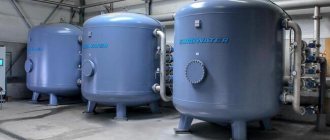
Hydraulic tanks for heating are painted red, tanks for water supply are painted blue. Expansion tanks for heating are usually smaller in size and lower in price. This is due to the membrane material - for water supply it must be neutral, because the water in the pipeline is potable.
Two types of hydraulic accumulators
Depending on the type of arrangement, hydraulic accumulators can be horizontal or vertical. Vertical ones are equipped with legs; some models have plates for hanging on the wall. It is the elongated upward models that are most often used when independently creating water supply systems for a private home - they take up less space. The connection of a hydraulic accumulator of this type is standard - through a 1-inch outlet.
Horizontal models are usually equipped with pumping stations with surface-type pumps. Then the pump is placed on top of the tank. It turns out compact.
Hydraulic tank design
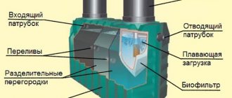
The design of the hydraulic accumulator is not complicated; it consists of a metal tank with a built-in pear-shaped membrane or a flat rubber diaphragm. The diaphragm is attached across the body between its halves, a pear-shaped cylinder is installed at the inlet near the neck - this type is used to supply water for individual water supply. A nipple is installed in the rear part of the metal container, with the help of which air is pumped into the hydraulic tank body, adjusting its internal pressure to the system.
Hydraulic tanks are produced for heating systems, hot water (red) and cold water supply (blue). Depending on the volume of the hydraulic tank and the installation method, there are models with a horizontal arrangement and volumetric vertical units that are installed on legs.
Horizontal models of small capacity are more often used in pumping stations with a built-in surface-type centrifugal electric pump and elements of an automatic control system. Vertical hydraulic tanks are used separately; they are more convenient to install when working with submersible electric pumps. Vertical tanks are structurally different from horizontal models: the membrane shell is attached to the upper and lower parts of the body, in addition to the nipple for pumping air, they have an additional fitting for bleeding it out of the rubber shell.
When purchasing a hydraulic tank, you should know that its useful volume when liquid accumulates is no more than 30% of the total.
Rice. 2 Hydraulic tank design
Operating principle of a hydraulic accumulator
Operating principle of a hydraulic accumulator.
When there is air inside the structure, the standard pressure is 1.5 atm. When the pumping equipment is turned on, water is pumped into the container. The more fluid enters, the more the free space of the hydraulic tank is compressed.
When the pressure reaches a given level (for 1-story dachas - 2.8-3 atm.), the pump is turned off, which stabilizes the work process. If you open the tap at this time, water will flow from the tank until the pressure level in the water supply drops to 1.6-1.8 atm. After this, the electric pump turns on and the entire cycle starts again.
If the water consumption is high, the well unit will pump water in transit, it will not enter the hydraulic tank - it is filled only after the taps are closed.
Automation is responsible for turning on the surface and deep pumps depending on the specified indicators. This is a pressure gauge and pressure switch, thanks to which the operation of the equipment is optimized.
Operating principle of the hydraulic tank
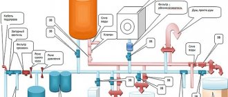
Typically, the inner bulb is located in a container of air at a standard pressure of 1.5 bar. When turned on, water is supplied by an electric pump installed in the well into the tank, filling the rubber bulb - it increases in volume, compressing the air space inside. When the pressure (standard 3 bar) reaches the threshold of the automatic relay, the electric pump turns off and the flow of water into the line stops.
When turned on, water flows to the consumer under pressure created by a rubber membrane compressed by air. Upon reaching the minimum level of 1.7 bar. the relay closes the power supply circuit of the electric pump and the line is filled.
Fig. 3 Example of installing a hydraulic accumulator in a water supply system with a submersible pump
How to choose the right hydraulic tank
A hydraulic tank is a container whose main working body is a membrane. Its quality determines how long the device will last from the moment of connection to the first repair.
Products made from food-grade (isobutane) rubber are considered the best. The metal of the product body is important only for expansion tanks. Where water is contained in the pear, the characteristics of the metal are not decisive.
If you don’t pay special attention to the thickness of the flange of your purchase, then in a year and a half, and not in 10-15 years, as you plan, you will have to buy a completely new device or, at best, change the flange itself
When choosing a device, special attention should be focused on the flange, which is usually made of galvanized metal. The thickness of this metal is very important. With a thickness of only 1 mm, the service life of the product will be no more than 1.5 years, since a hole will certainly form in the metal of the flange, which will damage the entire device.
Moreover, the warranty on the tank is only a year with a stated service life of 10-15 years. So the hole will appear just after the warranty period expires. And it will be impossible to solder or weld thin metal. You can, of course, try to find a new flange, but most likely you will need a new tank.
To avoid such misfortunes, you should look for a tank whose flange is made of stainless steel or thick galvanized steel.
Calculation of hydraulic tank parameters
In most cases of inclusions, hydraulic tanks for water supply are installed according to the principle: the larger the volume, the better. But too large a volume is not always justified: the hydraulic tank will take up a lot of useful space, the water will stagnate in it, and if power outages happen very rarely, there is simply no need for it. A hydraulic tank that is too small is also ineffective - if a powerful pump is used, it will turn on and off frequently and quickly fail. If a situation arises when installation space is limited or financial resources do not allow you to purchase a large-capacity storage tank, you can calculate its minimum volume using the formula below.
How to correctly calculate the volume of a hydraulic tank in a water supply system
Another calculation method is to calculate the required volume of the hydraulic tank based on the power of the electric pump used.
Recently, modern high-tech electric pumps with soft start and stop, frequency control of the speed of rotation of the impellers depending on water consumption have appeared on the market. In this case, there is no need for a large-volume hydraulic tank - soft start-up and adjustment do not cause water hammer, as in systems with conventional electric pumps. Automatic control units of high-tech devices with frequency control have a built-in hydraulic tank of a very small volume, designed for its pump group.
Table of calculated values of pressure and volume of the hydraulic tank depending on the operating modes of the water supply line
Accumulator volume
Do not buy a hydraulic accumulator based on what your friends or neighbors in the country have installed. Perhaps this model will not be effective for you. The volume of the hydraulic accumulator (like all other equipment!) should be selected only on the basis of the results of hydraulic calculations. The number of models on the market is quite large.
Is there an optimal hydraulic tank volume? As we have already said, only a hydraulic calculation can accurately indicate a specific model of hydraulic equipment that is optimally suited to your conditions. But the number of typical volumes for various models of hydraulic tanks is not so large. That is, if, according to the calculation results, you need a tank with a volume of 51.5 liters, then you will not be able to find such a tank on sale. You will be advised to purchase a 60 liter hydraulic tank. Extra liters of volume will not harm, and will even slightly increase the water supply and reduce the number of pump starts.
The experience of engineers selecting and installing water-lifting equipment tells us the following:
- A hydraulic accumulator with a volume of 25 liters can be installed in a water supply system for three consumers with a borehole pump productivity of 2 m3/h.
- in a system with a number of consumers of 4-8 and a pump capacity of 3.0-3.5 m3/h, a hydraulic tank with a volume of 60 liters is optimal.
- if the number of consumers is more than 10 and the pump capacity is 5 m3/h, then the optimal tank volume will be 100 liters.
How to connect a hydraulic tank
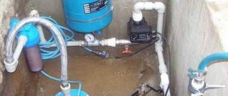
In addition to the pump and hydraulic tank, you will need a pressure switch and a pressure gauge. In accordance with the diagram for connecting the hydraulic accumulator to the water supply system, all these elements interact through a five-pin fitting. A tank with relays and instrumentation is installed in the boiler room or other room.
Dry-running relays and check valves are used as additional equipment for the system. These devices are responsible for ensuring that there is always water in the pipes and that it does not flow into the well or borehole. But this is when we are talking about individual water supply systems. After installation, it is necessary to carry out commissioning work, which consists of checking the tightness of connections and adjusting the hydraulic tank.
The established operating parameters are 1.7 bar. At the same time, the pumping equipment is turned on. The relay is set so that it switches off at 2.8 bar. These parameters are considered ideal for most models. Information can be found in the operating instructions for the hydraulic accumulator with pump.
Connection to a pumping station
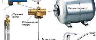
In this case, work on connecting the hydraulic accumulator to an autonomous water supply system is carried out simultaneously with the installation of automation and adapters. The most common installation cases require the following components:
- pressure gauge;
- five-inlet fitting;
- switching hydraulic relay (pressure switch).
If a submersible pump is used to draw water, the well piping must be equipped with a check valve and a dry inlet relay. If a simpler surface centrifugal pump is used to pump water, it is cheaper and more expedient to buy an assembled pumping station rather than install individual elements. The second option is preferable for those who have little experience but want to install the pump themselves.
Two hydraulic tanks for one pump
Connecting two (or more) hydraulic tanks is a common problem for people faced with a forced increase in water consumption. If the volume of one tank turns out to be too small, installing an additional hydraulic accumulator is not very burdensome.
Additional elements can be installed parallel to the existing system: it is enough to use another adapter fitting, flexible hose or water pipe. A system with two (or more) tanks is both a rational solution and an excellent safety net. If the membrane fails in one of the tanks, you can still use the pump, but not in intensive mode. Such a system will provide enough time to replace the faulty unit.
To submersible pump
You can guess that we are talking about a pump that is immersed in the aquifer of a well or well. For uninterrupted water supply, such a system must be equipped with a check valve: this device will not allow the pumped out water to return to the bottom of the well after use. Accordingly, the pump will not run idle and will last much longer.
In most cases, the check valve is already installed on the pump; additional installation may be required during the repair process. To avoid being left without water for an indefinite period of time, it is recommended to purchase a pump with a spare valve, which is sold separately or supplied with the pump.
Another important point is the quality of the pressure pipeline: since the pipe lies at a fairly large depth, a possible breakdown may not be noticed immediately.
The first sign of problems with the pipeline is a sharp drop in pressure; the accumulator takes longer to fill with water; over time, this gap may increase.
To surface pump
Connecting a hydraulic accumulator to a system with an external centrifugal pump also has its own nuances, namely:
- first of all, you need to check the internal pressure of the tank: it should not exceed 1 bar;
- To prepare for connection, you will need a five-pin fitting. This small but very important part combines the accumulator itself, a pipeline, a pressure switch, a pressure gauge and an external pump. Before the actual installation process, you need to stock up on sealing materials (sealant or plumbing tape);
- to connect the fitting to the tank, use a rigid hose or flange with a bypass valve;
- after installing the tank, it is worth installing the remaining elements: pressure gauge, relay, water supply leading to the pump unit;
- before starting operation, a series of on and off cycles should be carried out to identify possible leaks;
- if something goes wrong, you need to find out the cause of the problem and, if necessary, repeat the entire installation cycle again.
Connection to water heater
The hydraulic accumulator in a system with a storage water heater acts as an expansion tank. As water heats up, it increases in volume, which also increases the load on the water supply. Since pressure increases in a confined space, the process can become very critical, and the temperature decrease is unacceptable. There is a need to transfer this excess pressure somewhere. This is where the hydraulic accumulator comes to the rescue. Excess heated water will go into the hydraulic tank, which will normalize the pressure in the system. Further, the water from the expansion tank can be used for domestic purposes.
Types of membrane tanks
Hydraulic tanks can be installed in water supply systems for various purposes.
In particular, we are talking about the following:
- Meeting the need for hot and cold water.
- Heating systems for a private house.
In the first case, the membrane tank allows you to extend the service life of pumping equipment due to the established on and off mode and protects the system from the destructive effects of water hammer. The second option involves using a hydraulic tank as an expander, which is built into a closed heating system and is its integral part.
According to their configuration, hydraulic tanks are divided into horizontal and vertical models. It is worth noting that the configuration of the tank does not affect the principle of its operation and the connection of the submersible pump to the accumulator.
A distinctive feature of vertical type hydraulic tanks is a special valve through which excess air is released. Moreover, in most cases, models with a volume of more than 50 liters are equipped with a valve. The valve is mounted precisely in the upper part of the container, since the air entering the membrane compartment along with water tends to accumulate at the top of the chamber.
Horizontal tanks also have a device for bleeding air, only in this case the drain device or tap is located behind the accumulator. To remove air from a small container, drain the water completely.
When looking for an answer to the question of where to install a hydraulic accumulator for water supply systems, it is important to understand that horizontal and vertical devices are characterized by the same efficiency and functionality. Therefore, when choosing a device, first of all, the dimensions of the room where the device is planned to be installed are taken into account.
Nuances of connecting a hydraulic accumulator
A device with a pear-shaped container assumes that there is water inside it, not air. This feature gives an advantage over the modification with a flat membrane. The reason is that in the latter case the liquid comes into contact with the metal from which the tank body is made. As a result, pockets of corrosion appear. This must be taken into account when choosing a model.
In addition, the bulb is easier to replace if it fails. This usually happens 10-15 years after connecting the circulation pump with a hydraulic accumulator. In addition to the problem of selection, the following aspects must be taken into account during installation:
- The mounting point should be located at the highest possible height. Ideally, this is the attic of the house. This factor allows you to increase the pressure in the pipeline.
- Despite the fact that the flanges are galvanized and the body is painted, the room where the accumulator is installed must be dry. High humidity will lead to condensation, rust and premature equipment failure.
- It is better to connect using flexible stainless steel braided hoses. It should be secured with inch nuts.
- The inlet pipe is where the coarse filter is inserted, which will prevent rust, scale and other suspended solids from entering the container and damaging the membrane.
- A ball valve is mounted at the inlet, with which you can cut off the wiring from the supply line if you need to repair it or service the pump. There will be no water in the house.
Before purchasing, it is necessary to make preliminary calculations. They consist in determining the required operating parameters and characteristics of the hydraulic tank. Be sure to watch this video, where the person tells you how to choose a tank yourself.
The opinion “the larger the capacity, the better” is incorrect. Too much water will cause it to stagnate. As a result, harmful bacteria may multiply, sediment may form, and an unpleasant odor may appear. Such a tank takes up a lot of space and weighs heavily. If the consumption is small and the power is rarely turned off, purchasing such equipment is not practical.
A tank that is too small is ineffective because the pump will turn on frequently, which will adversely affect service life. A special formula is used for calculations. An alternative method for determining the required tank volume is to match the power of the pumping station and the size of the tank. More productivity - larger tank size.
For this purpose, special tables are used. If the conditions are completely cramped, it makes sense to consider purchasing a pump with a soft start, and not spend money on a hydraulic accumulator. But if it is possible to install both elements, the benefits will also include savings. But most importantly, such a system will work for a long time and without interruption.
Installing a hydraulic accumulator
After purchasing a suitable model of electric pump for a well or well and connecting it to the pipeline, calculating the volume and purchasing the required hydraulic tank, you need to install it correctly. If the model has a large volume and is installed on vertical legs, you should use the following recommendations:
- It is better to install a volumetric storage tank at the highest point of the house (attic, second floor) - this will create maximum pressure in the water line.
- The floor in the room must be level, humidity must not exceed established standards in order to avoid corrosion of the galvanized flange and surface of the tank.
- It is better to connect the device using a flexible pressure hose in a stainless steel braid and one-inch diameter union nuts made of brass. Avoid supply hoses with aluminum braiding and mounting couplings made from cheap silumin, a brittle alloy of aluminum and silicon.
Rice. 10 Connection diagram of the hydraulic accumulator to the pump and water supply system
Expansion tank piping
Before connecting a hydraulic accumulator for individual water supply systems, prepare components: automatic devices, filters and adapter couplings for connecting HDPE pipes. After connecting the electric pump to the HDPE water supply using plastic adapter couplings and placing it in the well, further assembly work is carried out in the following sequence:
- At the outlet of the water pipe from the pump, a ball valve and a coarse filter are installed to remove sand from the water.
- After the filter, a tee with a hole diameter suitable for connecting automation is installed. An adapter coupling is screwed into its upper outlet to connect the relay.
- To connect the pressure switch and pressure gauge to the electric pump, a standard five-inlet fitting is used, which is connected to the tee using an adapter.
- At the outlet of a fitting with an external thread with a diameter of 1 inch, a ball valve with a union nut is installed - this will allow repairs and replacement of components without draining the water from the entire water main.
- A hydraulic accumulator is connected to the outlet of the fitting with a 1-inch internal thread using a flexible liner.
- Next, a pressure gauge and a pressure switch are installed in the five-pin fitting, and a dry-running relay is screwed into the tee.
- At the end, connect the electrical power cable to the relay - installation of the automation can be considered complete.
Many people prefer to install all automation using connecting fittings directly at the outlet of the accumulator - this technique does not require an underwater hose.
The hydraulic tank is the main component in automatic control systems for electric pumps, necessary to reduce the load on the water main and reduce the operation cycles of pumping equipment. Its connection to the pipeline and adjustment are quite easy to do with your own hands using the simplest plumbing tools. To correctly select an expansion tank, you can use a not too complicated formula or determine its parameters approximately depending on the flow volume or power of the pumping equipment.
Features of connecting the hydraulic tank to the water supply system
A hydraulic accumulator is not just a container filled with water. This is a special-purpose device that performs a special function in the water supply system. For this reason, installing the equipment may seem quite complicated.
When solving the problem of how to connect a hydraulic accumulator to a well, it is very important to take into account vibration and noise factors. Therefore, special rubber gaskets are used for fixation on the floor, and rubber adapters are used for fastening to the pipeline. In addition, it is important to understand that the outlet diameter of the liner can be much smaller.
Fill the new tank with the utmost care, being careful not to supply water under strong pressure. If the tank is not used for a long time after manufacturing, the membrane may cake. Strong pressure or sudden supply of water can cause damage to the membrane or its complete failure. Experts recommend bleeding all the air out of the bulb before filling, which will help avoid troubles when pumping water into the accumulator.
When choosing where to install the accumulator in the water supply system, it is necessary to ensure free access to any part.
The connection of the hydraulic accumulator to the water supply system is carried out according to a certain scheme:
- A water pipe is led into the house through the foundation or basement.
- A power cable is inserted to connect pumping equipment.
- Collect individual elements into one line.
- Adjust the hydraulic tank.
- Connect the device to the general water supply system.
- If it is necessary to use two hydraulic accumulators in the water supply system, an additional device is installed in the caisson.
- Connect the pressure gauge to the second device.
- If you intend to use a water supply branch for watering plantings, then install a check valve and a drain valve.
Setting up the hydraulic accumulator when connecting
Before using a water supply system with a hydraulic accumulator in a private house, you need to know what the pressure in the hydraulic accumulator should be for its optimal operation; take a portable pressure gauge to take readings. A typical water line with a standard pressure switch has response thresholds from 1.4 to 2.8 bar, the factory setting of the pressure in the hydraulic tank is 1.5 bar. To ensure that the hydraulic accumulator operates efficiently and is completely filled, the lower threshold for switching on the electric pump is selected at 0.2 bar for a given factory setting. more - a threshold of 1.7 bar is set on the relay.
If during operation or due to a long storage period it is determined that the pressure in the hydraulic tank is insufficient when measured with a pressure gauge, proceed as follows:
- Disconnect the electric pump from the power supply.
- Remove the protective cover and press the hydraulic tank valve in the form of a nipple head at the outlet of the device - if liquid comes from there, then the rubber membrane has been damaged and needs to be replaced. If air comes from the hydraulic tank, its pressure is measured using a car pressure gauge.
- Drain the water from the main by opening the tap closest to the expansion tank.
- Using a hand pump or compressor, pump air into the battery tank until the pressure gauge reads 1.5 bar. If, after automation, the water rises to a certain height (high-rise buildings), the total pressure and operating range of the system are increased based on the fact that 1 bar. equated to 10 meters of vertical water column.
When calculating the required pressure in the hydraulic tank for any range, select its value 10% less than the lower threshold of the relay operation. Selecting this value ensures that the built-in membrane will expand and contract within a small range and accordingly increase the service life of it and the entire expansion tank.
What should be the air pressure in the air cavity of the accumulator?
The pressure in the air cavity of the hydraulic accumulator should be 10% less than the pump activation pressure.
Moreover, the air pressure needs to be measured only with the tank disconnected from the system (without water pressure). Air pressure must be regularly monitored and, if necessary, brought back to normal; this will significantly extend the life of the membrane. For the same purpose, it is not recommended to make the pressure difference between turning the pump on and off too large. The optimal difference is 1.0-1.5 atm. Larger differences stretch (load) the membrane more, thereby reducing its service life, and moreover, large pressure differences are not comfortable when using water.
It is recommended to install hydraulic accumulators in places not subject to flooding and with low humidity. In this case, the accumulator flange will last much longer. Since the tank does not bear any load, there is no need for additional fastening. The hydraulic accumulator can simply be installed on the floor on standard supports.
When choosing a specific brand of hydraulic accumulator, you should pay attention to the membrane material, the availability of certificates and sanitary and hygienic certificates certifying that the hydraulic accumulator is intended for use in drinking water systems. It’s also a good idea to make sure you have spare membranes and flanges, so that in case of problems you don’t have to buy a completely new tank.
The maximum pressure for which the accumulator is designed should not be less than the maximum possible pressure in the system (for example, if the pressure switch breaks down). This is why most tanks are designed for a pressure of 10 bar.
The question often arises about how much water is in the accumulator?
For example, if the power goes out, how many liters of water can be used?
This value depends on the settings of the pressure switch. As you might guess, the higher the pressure difference between turning the pump on and off, the more water will enter the accumulator, however, this difference must be limited for the reasons stated above.
As an example, we provide a table of the filling capacity of hydraulic accumulators.
| P air, bar | 0,8 | 0,8 | 1,8 | 1,3 | 1,3 | 1,8 | 1,8 | 2,3 | 2,3 | 2,8 | 2,8 | 4,0 |
| P on pump, bar | 1,0 | 1,0 | 2,0 | 1,5 | 1,5 | 2,0 | 2,0 | 2,5 | 2,5 | 3,0 | 4,0 | 5,0 |
| P off pump, bar | 2,0 | 2,5 | 3,0 | 2,5 | 3,0 | 2,5 | 4,0 | 4,0 | 5,0 | 5,0 | 8,0 | 10,0 |
| Total tank volume, l | Water reserve, l | |||||||||||
| 19 | 5,70 | 7,33 | 4,43 | 4,99 | 6,56 | 2,53 | 7,09 | 5,37 | 7,46 | 6,02 | 8,11 | 8,35 |
| 24 | 7,20 | 9,26 | 5,60 | 6,31 | 8,28 | 3,20 | 8,96 | 6,79 | 9,43 | 7,60 | 10,24 | 10,55 |
| 50 | 15,00 | 19,29 | 11,67 | 13,14 | 17,25 | 6,67 | 18,67 | 14,14 | 19,64 | 15,83 | 21,33 | 21,97 |
| 60 | 18,00 | 23,14 | 14,00 | 15,77 | 20,70 | 8,00 | 22,40 | 16,97 | 23,57 | 19,00 | 25,60 | 23,36 |
| 80 | 24,00 | 30,86 | 18,67 | 21,03 | 27,60 | 10,67 | 29,87 | 22,63 | 31,43 | 25,33 | 34,13 | 35,15 |
| 100 | 30,00 | 38,57 | 23,33 | 26,29 | 34,50 | 13,33 | 37,33 | 28,29 | 39,29 | 31,67 | 42,67 | 43,94 |
| 200 | 60,00 | 77,14 | 46,67 | 52,57 | 69,00 | 26,67 | 74,67 | 56,57 | 78,57 | 63,33 | 85,33 | 87,88 |
| 300 | 90,00 | 115,71 | 70,00 | 78,86 | 103,50 | 40,00 | 112,00 | 84,86 | 117,86 | 95,00 | 128,00 | 131,82 |
| 500 | 150,00 | 192,86 | 116,67 | 131,43 | 172,50 | 66,67 | 186,67 | 141,43 | 196,43 | 158,33 | 213,33 | 219,70 |
| 750 | 225,00 | 289,29 | 175,00 | 197,14 | 258,75 | 100,00 | 280,00 | 212,14 | 294,64 | 237,50 | 320,00 | 329,55 |
| 1000 | 300,00 | 385,71 | 233,33 | 262,86 | 345,00 | 133,33 | 373,00 | 282,86 | 392,86 | 316,67 | 426,67 | 439,39 |
According to this table, in a 200 liter hydraulic accumulator with the following pressure switch settings: Pump on - 1.5 bar Pump off - 3.0 bar Air pressure - 1.3 bar
The water supply will be 69 liters, which is approximately a third of the total volume.
In conclusion, a few words about the required volume of the hydraulic accumulator.
V t = K x A max x ((P max +1) x (P min +1)) / (P max - P min) x (P air + 1)
A max - estimated maximum water flow (liter/min) K - coefficient depending on the power of the pump electric motor (see table below) P max - pump switch-off pressure, bar P min - pump switch-on pressure, bar P air. — pressure in the air cavity of the hydraulic accumulator, bar
| Pump power, kW | 0,55-1,5 | 2,2-3,0 | 4,0-5,5 | 7,5-9,0 | ||||||||
| Factor K | 0,25 | 0,375 | 0,625 | 0,875 | ||||||||
We will select the minimum required volume of the hydraulic accumulator for the water supply system based on the Aquarius BTsPE 0.5-50 U pump with the following settings:
P max = 3.0 bar P min = 1.8 bar P air. = 1.6 bar A max = 2.1 m³/h (35 l/min) K = 0.25 (since the pump power is in the range of 0.55–1.5 kW)
V t = 31.41 liter
We select the next closest volume of the hydraulic accumulator - 35 liters.
Note that the tank volume of 24-50 liters is in excellent agreement with other methods for calculating hydraulic accumulators for domestic water supply systems and empirical recommendations of various manufacturers of pumping equipment.
A larger volume should be chosen if there are frequent power outages, but it must be remembered that in any case, water fills approximately a third of the total volume (see the occupancy table above). And of course, the more powerful the pump is installed in the system (relevant for pumps with a power of 1.1 kW and above), the larger the size of the hydraulic accumulator should be preferred, this will reduce the number of repeated short-term starts and extend the service life of the pump motor.
When purchasing large-volume hydraulic accumulators, you must be aware that water must be used regularly, since with prolonged inactivity, its quality begins to deteriorate. After all, using all the water from a hydraulic accumulator with a volume of 24 or 50 liters is much easier and faster than from a 100 or 200 liter one.
Models and prices for hydraulic accumulators can be found in the section “
And one question remained unclear: when to inflate the accumulator with air, before filling with water or after? Logically, it seems that you need to pump up before, but after searching the answer on the Internet, it turned out that some recommend doing this after.
In general, it is correct to pump the accumulator dry until it is filled with water.
To calculate the required pressure in the air part of the accumulator, you can use formulas; if you are lazy, then the air pressure in the accumulator is calculated using a very simple formula, it should be 10% less than the pressure at which the pressure switch turns on the pump. Typical values of the minimum and maximum pressure values at which the pump turns on and off are 1.5 and 3 bar, subtract 10% from 1.5 bar and get 1.35 bar of air we need to pump into the accumulator.
If you don’t like this calculation, you can use a more scientific approach:
Also keep in mind that the hydraulic accumulator requires periodic maintenance. Water always contains a small part of dissolved air, and this air gradually reduces the useful volume of the bulb (rubber membrane) in the accumulator. On large-capacity hydraulic accumulators, as a rule, there are special valves for releasing this air; in small hydraulic accumulators, which are usually equipped with household pumping stations, there are no such valves, and to remove air from the membrane, a simple operation must be performed every couple of months.
1. It is necessary to turn off the power to the pump and drain all the water from the accumulator; it is best, of course, to provide a special tap for this, or use the tap closest to the accumulator.
2. The procedure from point 1 must be done 2-3 times in a row.
And please do not confuse the hydraulic accumulator and the water storage tank, these are different devices, the hydraulic accumulator is designed to reduce the number of pump starts, and as a result increase its service life, as well as to protect against water hammer; in the event of a power outage, the hydraulic accumulator will of course supply water for some time you with water, but I wouldn’t count on much. In case of power outages or water supply breakdowns, a storage tank is needed.
Pressure switch
- an element that controls the operation of a pumping station (for example AQUAJET or AQUAJET-INOX) and which makes it possible to operate it in automatic mode. The pressure switch has several characteristics:
- Turn-on pressure
(
P on
) is the pressure (bar) at which the pumping station is turned on by closing the contacts in the pressure switch. Sometimes the switching pressure is also called “lower” pressure. - Switch-off pressure
(
P off
) is the pressure (bar) at which the pumping station is switched off by opening the contacts in the pressure switch. Sometimes the shutdown pressure is also called “upper” pressure. - Pressure drop
(
ΔP
) is the absolute difference between the cut-out pressure and the cut-in pressure (bar). - The maximum shutdown pressure
is the maximum pressure (bar) at which the pumping station can be turned off.
Any pressure switch has factory settings and, as a rule, they are as follows: Switch-on pressure: 1.5-1.8 bar Switch-off pressure: 2.5-3 bar Maximum switch-off pressure: 5 bar
How it all works:
Let’s say the pumping station is connected (more on this in the article “Preparing the DAB pumping station for operation”), and the entire system is filled with water. After opening any tap (shower, sink, etc.) and starting to draw water, the pressure in the system will begin to drop smoothly (thanks to the membrane hydraulic tank), which is easy to track with a pressure gauge. All this time, water is supplied to the consumer from the hydraulic tank. When the “lower” switching pressure is reached (it can also be monitored by a pressure gauge at the moment the pump is switched on), the contacts inside the pressure switch will close and the pump will start. The rest of the time of water collection, the pump continues to operate, supplying water directly to the consumer. After the water withdrawal is completed (all taps are closed), the pump still continues to work, only now the water is not supplied to the consumer, but is pumped into the hydraulic tank (since it has nowhere else to go) and the pressure gradually increases. When the shutdown pressure is reached (can be easily monitored on the pressure gauge when the pump stops), the contacts inside the pressure switch open and the pump stops. At the next water draw, the cycle repeats. It's quite simple.
But what to do if the factory settings of the pressure switch are not very comfortable? For example:
on the upper floors the pressure drops very noticeably, or the water purification system requires at least 2.5 bar at the inlet, while the pump turns on only at 1.5-1.8 bar.
Optimal air pressure
For household appliances to work normally, the pressure in the hydraulic tank must be in the range of 1.4-2.8 atm. For better preservation of the membrane, it is necessary that the pressure in the water supply system be 0.1-0.2 atm. exceeded the pressure in the tank. For example, if the pressure inside the membrane tank is 1.5 atm, then in the system it should be 1.6 atm.
It is this value that should be set on the water pressure switch, which works in conjunction with the hydraulic accumulator. For a one-story country house, this setting is considered optimal. If we are talking about a two-story cottage, the pressure will have to be increased. To calculate its optimal value, use the following formula:
Vatm.=(Hmax+6)/10
In this formula V atm. is the optimal pressure, and Hmax is the height of the highest water intake point. As a rule, we are talking about the soul. To get the required value, you should calculate the height of the shower head relative to the accumulator. The obtained data is entered into the formula. As a result of the calculation, the optimal pressure value that should be in the tank will be obtained.
Please note that the obtained value should not exceed the maximum permissible characteristics for other household and plumbing appliances, otherwise they will simply fail.
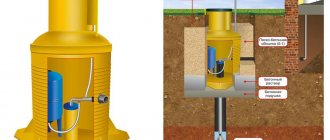
If we talk about an independent water supply system at home in a simplified way, then its components are:
- pump,
- hydraulic accumulator,
- pressure switch,
- check valve,
- pressure gauge
The last element is used to quickly control the pressure. Its constant presence in the water supply system is not necessary. It can only be connected at the moment when test measurements are being made.
When a surface pump is involved in the circuit, the hydraulic tank is mounted next to it. The check valve is installed on the suction pipeline, and the remaining elements form a single bundle, connecting to each other using a five-pin fitting.
The five-pin device is ideal for this purpose, since it has leads of different diameters. The incoming and outgoing pipelines and some other elements of the connection can be connected to the fitting using American connectors to facilitate preventive and repair work on individual sections of the water supply system.
However, this fitting can be replaced with a bunch of connecting elements. But why?
In this diagram, the connection order is clearly visible.
When connecting the fitting to the hydraulic accumulator, you need to make sure that the connection is tight. So, the hydraulic accumulator is connected to the pump as follows:
- one inch lead connects the fitting itself to the hydraulic tank pipe;
- a pressure gauge and pressure switch are connected to the quarter-inch terminals;
- There are two free inch terminals left, to which the pipe from the pump is mounted, as well as the wiring going to the water consumers.
If a surface pump operates in the circuit, then it is better to connect the hydraulic accumulator to it using a flexible hose with a metal winding.
The hydraulic accumulator is connected to the submersible pump in exactly the same way. A feature of this circuit is the location of the check valve, which has nothing to do with the issues we are considering today.
Hydraulic accumulator device
The sealed body of this device is divided by a special membrane into two chambers, one of which is intended for water and the other for air.
Water does not come into contact with the metal surfaces of the body, since it is located in a water chamber-membrane made of a strong butyl rubber material that is resistant to bacteria and meets all hygienic and sanitary standards for drinking water.
The air chamber contains a pneumatic valve, the purpose of which is to regulate pressure. Water enters the accumulator through a special threaded connection pipe.
The hydraulic accumulator device must be mounted in such a way that it can be easily disassembled in case of repair or maintenance, without draining all the water from the system.
The diameters of the connecting pipeline and the pressure pipe should, if possible, coincide with each other, then this will avoid unwanted hydraulic losses in the system pipeline.
In the membranes of hydraulic accumulators with a volume of more than 100 liters there is a special valve for bleeding air released from the water. For small-capacity hydraulic accumulators that do not have such a valve, the water supply system must have a device for bleeding air, for example, a tee or tap that shuts off the main line of the water supply system.
In the air valve of the hydraulic accumulator, the pressure should be 1.5-2 atm.
Injecting water into the hydraulic accumulator
When the correct air pressure has already been set, you can connect the accumulator to the system. After connecting it, you need to carefully observe the pressure gauge. All hydraulic accumulators indicate normal and maximum pressure values, exceeding which is unacceptable. Manual disconnection of the pump from the network occurs when the normal pressure of the accumulator is reached, when the limit value of the pump pressure is reached. This occurs when the increase in pressure stops.
The pump power is usually not enough to pump the tank to the limit, but this is not even particularly necessary, because when pumping, the service life of both the pump and the bulb is reduced. Most often, the pressure limit for switching off is set 1-2 atm higher than switching on.
For example, when the pressure gauge reads 3 atm, which is sufficient for the needs of the owner of the pumping station, you need to turn off the pump and slowly rotate the nut of the small spring (delta P) to decrease until the mechanism is activated. After this, you need to open the tap and drain the water from the system. While observing the pressure gauge, you need to note the value at which the relay turns on - this is the lower pressure limit when the pump turns on. This indicator should be slightly higher than the pressure in an empty accumulator (by 0.1-0.3 atm). This will make it possible to serve the pear for a longer period of time.
When the nut of the large spring P rotates, the lower limit is set. To do this, you need to turn on the pump and wait until the pressure reaches the desired level. After this, it is necessary to adjust the nut of the small spring “delta P” and complete the adjustment of the accumulator.
How does a hydraulic accumulator work?
The principle of the hydraulic accumulator is simple, like everything ingenious. A rubber gasket of conical, pear-shaped or other shape is inserted into the body of the metal tank.
The gasket or membrane is most often made of butyl, which has a significant margin of strength and is resistant to constant stretching and exposure to water.
This material is also characterized by high antibacterial properties and meets all hygiene standards. The water entering the container is retained by this gasket and does not come into contact with the walls of the metal body.
A nipple is installed on the back of the housing, which allows air to be pumped into the container.
Image gallery
Photo from
Hydraulic tank as part of a factory-assembled pumping station
Hydraulic accumulator in a circuit with a submersible pump
Functions and purpose of hydraulic tanks in water supply
Rules for proper operation of hydraulic accumulators
Water and air are separated by a gasket. By pumping or bleeding air, you can regulate the pressure it exerts on the water. As a result, water enters the system under pressure, and this provides the necessary pressure.
A mandatory element for a hydraulic accumulator is a pressure gauge, which is used to control the current pressure in the tank. The optimal pressure in the air compartment of the hydraulic accumulator is considered to be 1.5-2.0 atmospheres.
The diagram clearly shows the structure of the hydraulic accumulator. Water enters the upper part, which is held by a rubber membrane, and air is pumped into the lower part, which provides the necessary water pressure
Wherever good pressure is needed, installing a hydraulic accumulator will be more than relevant. And the requirements for good pressure are constantly increasing.
For example, for normal operation of an automatic washing machine or dishwasher, at least 0.7-2 atmospheres may be needed. A shower cabin with hydromassage or the famous bathtub with a jacuzzi will work normally only at four atmospheres.
It’s worth noting right away that excess pressure in the plumbing system is not the most useful phenomenon, since this creates an additional and completely unnecessary load on the structure.
This reduces their service life and leads to leaks, breakdowns and other problems. Although during pressure testing of the system the pressure can reach even 10 atmospheres, performance indicators are best left at 4-5 atmospheres.
Hydraulic accumulators vary in volume, and they can also be oriented horizontally or vertically. Hydraulic tanks designed to operate at high temperatures are designed for heating systems
Even if the house does not have modern household appliances that are sensitive to water pressure in the water supply, a hydraulic accumulator can still come in handy. On the upper floors of high-rise buildings, the water pressure in the water supply can be very, very weak. A hydraulic accumulator can effectively solve this kind of problem.
The capacity of the hydraulic accumulator can vary between 5-100 liters. Of course, these are very modest numbers to store water. If there is a need to always have a solid supply of water, it is better to use a storage tank of sufficient volume.
When organizing an autonomous water supply, a hydraulic accumulator is used in combination with a surface or submersible pump. The device pumps water into the tank until the pressure reaches a certain, predetermined level. After this, the equipment turns off automatically.
The water decreases, the pressure decreases, and reaches a minimum level. At this moment, the pump turns on again and runs until the previously emptied container is filled with water.
To regulate the operation of such a system, a pressure switch is used. This allows you to reduce the number of switches on/off of pumping equipment to a minimum, which significantly increases its service life.
The inlet for supplying water to the accumulator is equipped with a special pipe, which is installed on a threaded connection.
Image gallery
Photo from
Accumulator housing material
Flange with threaded fitting
Hydraulic tank air valve - nipple
Hydraulic accumulator platform
Modern models are relatively easy to disassemble and then reassemble, performing the necessary maintenance, replacing parts or other types of repairs. If the accumulator is installed correctly, then for its maintenance there is no need to drain water from the water supply system.
This table can be used to calculate the volume of the hydraulic tank for a specific situation, based on the predicted operating conditions (+)
When choosing a hydraulic accumulator, you should pay attention to the diameter of the pipe and compare it with the dimensions of the water pipe. Experts assure that the more accurate these indicators are, the less hydraulic losses there will be in the system. If the diameters of the structures do not match, you will have to use an adapter.
Water tends to evaporate, which can affect the pressure readings in the device. To bleed off such excess air, a valve is installed on large-capacity hydraulic accumulators - about 100 liters.
Small volume models do not have such a device. It is recommended to install a valve or tee in the system, which will shut off the water supply to the water supply and allow excess air to be removed.
Rules of operation and repair
Connecting and setting up the hydraulic accumulator correctly is only half the battle. In order for the device to operate for a long time, it must be properly operated and periodically performed preventive inspection and maintenance.
Instructions require medical examinations to be carried out twice a year, but practice shows that this is not enough. The condition of the hydraulic accumulator should be checked every three months. At the same frequency, it is advisable to monitor the settings of the pressure switch in order to correct them if necessary.
Incorrect operation of the relay creates additional loads on the entire system, which can also affect the condition of the accumulator.
If during inspection dents or traces of corrosion are found on the device body, these damages must be repaired. It is best to do this as early as possible, otherwise corrosion processes will develop, which can lead to damage to the integrity of the accumulator body.
An important preventive measure is checking the pressure in the hydraulic tank itself using a pressure gauge. If necessary, the required amount of air should be pumped into the device or excess air should be vented.
If this does not help and the new pressure gauge readings do not correspond to those expected, it means that either the integrity of the accumulator body is compromised or its membrane is damaged.
If the membrane installed in the accumulator is worn out, you can try to replace it with a new one. To do this, the device will have to be dismantled and disassembled.
Some craftsmen manage to detect and repair areas of damage to the body, but such repairs are not always durable and reliable. The rubber liner or membrane is the weak point of the accumulator. Over time it wears out.
You can replace the membrane with a new element at home, but to do this you will have to completely disassemble and reassemble the hydraulic accumulator.
When choosing a suitable location for installing a hydraulic accumulator, you should remember that it must be spacious enough to carry out maintenance of the device
If a home craftsman doubts his abilities in this area or does not have sufficient experience, he can cause even more damage to the device than the previous breakdown. In such a situation, it is better to contact a service center.
Scheme of water supply for a private house from a well with a hydraulic accumulator
If there is a well on a personal plot, water is taken from it. The main thing is that the hydraulic structure has a sufficient supply of water and is located away from sources of pollution. The advantage of a well over a well is that in the event of a power outage, the “classic” bucket and rope come to the aid of the homeowner.
The water supply scheme for a dacha with a hydraulic accumulator from a well can be divided into four conventional parts:
- Pump. In wells deeper than 9 m, submersible pumps are used. They are suspended on cables so that at least 50 cm remains to the bottom. In addition to the pressure gauge and pressure switch, to ensure safe operation of the pump, it is recommended to use a dry-running sensor.
- Pipe for supplying water to the house. Attaches to the pump. A trench for the pipe is dug below the soil freezing level.
- Hydraulic accumulator. The volume of the tank is calculated based on the number of consumers.
- House wiring. Distributes the water supply to the right points in the home. The center of the system can be, for example, a boiler room, which also houses a hydraulic accumulator and a water heater. From here the distribution pipes go to other rooms - bathroom, toilets, kitchen, etc.
The configuration of the system inside the house depends on the needs of the family. So, if the dacha is operated in winter, then a heating boiler is included in the scheme. A ready-made system design makes it easier to prepare an estimate for installation work and determine the cost of components.
Assembling a water supply diagram from a well
Before installing the pump, it is advisable to repair and insulate the well. The work includes sealing seams, installing a bottom filter and external protection (drainage and thermal insulation). The line from the pump to the house is made of polypropylene or polyethylene pipes for outdoor use with a diameter of at least 32 mm.
The water supply scheme inside the dacha can be sequential or parallel. The first option is suitable for buildings with 2-3 water intake points. In other cases, it is better to choose parallel wiring with the collector. It ensures equal pressure at all points of water consumption. Instead of steel pipes, metal-plastic or propylene products are now used for internal wiring. The diameter of pipes for house wiring is 16-25 mm. It depends on the length of their sections, as well as the intensity of water withdrawal.
After entering the house, the supply pipe is connected to the hydraulic accumulator (the pressure switch is installed in front of the storage tank). A tee with shut-off valves and a pressure gauge is placed behind it. One of the tee pipes serves as a supply to the boiler, the second – to the cold water collector.
The system can be equipped with filters:
- rough cleaning (required) - after entering the supply line into the house;
- fine cleaning - after the hydraulic accumulator before distribution to cold and hot water systems;
- in-depth cleaning depending on the specific local conditions (coal, ion exchange, reverse osmosis) - in front of drinking water points or household appliances (washing machine, boiler, etc.).