Types of hydraulic tanks for water supply systems
Depending on the type of installation, hydraulic accumulators are divided into vertical and horizontal products. In the first case, the devices differ in that it is easier to find a suitable location for their installation. Both vertical and horizontal tanks are equipped with nipples.
At the same time as the water, a small amount of air enters the device. Over time, it accumulates inside and partially occupies the volume of the container. In order for the tank to function properly, it is necessary to periodically bleed the collected air through the nipple.
The way a vertical type hydraulic accumulator is designed allows the nipple to be used specifically for this purpose. In turn, with horizontal containers everything is more complicated. In addition to the nipple intended for bleeding air, a shut-off valve and an outlet into the sewer system must be installed on the pressure tank. All of the above applies to models that can accumulate liquid in excess of 50 liters.
If the tank is smaller, then the device, regardless of the type, does not have any special devices for removing air from the membrane. But it still needs to be removed from the hydraulic tank, so water is periodically drained from it, after which it is refilled with liquid.
This procedure is performed in the following sequence:
- First of all, turn off the power to the pumping equipment and pressure switch.
- Then open the nearest faucet.
- The water is drained until the tank is empty.
- Then the tap is closed, power is supplied to the relay and the pump, after which water fills the tank automatically.
For autonomously equipped engineering systems, two types of hydraulic accumulators are used for water supply - they come in blue and red. This feature allows them to distinguish tanks by purpose. The blue tank is used for the installation of cold water supply systems, and the red battery is used for the operation of the heating circuit.
When the manufacturer does not designate the product in one of these two colors, you can find out the purpose of the purchased device from the technical data sheet for the product.
In addition to color, the types of hydraulic accumulators for water supply differ depending on the characteristics of the materials used for the production of membranes. In any case, high-quality rubber is used, which is intended for contact with products. But in red tanks, membranes are installed that are designed for contact with hot water, and in blue tanks - with cold water.
How to properly adjust the pressure in the accumulator
Correct operation of the pumping station requires proper configuration of three main parameters:
- The pressure at which the pump turns on.
- Shutdown level of a functioning unit.
- Air pressure in the membrane tank.
The first two parameters are controlled by a pressure switch. The device is installed on the inlet fitting of the hydraulic accumulator. Its adjustment occurs experimentally; to reduce the error, the actions are performed several times. The relay design includes two vertical springs. They are mounted on a metal axle and secured with nuts. The parts differ in size: a large spring regulates the activation of the pump, a small one is required to set the difference between the upper and lower pressure. The springs are connected to a membrane that makes and opens electrical contacts.
The adjustment is made by turning the nut using a wrench. Clockwise rotation compresses the spring and increases the pump activation threshold. Turning counterclockwise weakens the part and reduces the response parameter. The adjustment procedure follows a certain pattern:
- The air pressure in the tank is checked and, if necessary, pumped up with a compressor.
- The nut of the large spring turns in the desired direction.
- The water drain valve opens. The pressure drops, at a certain moment the pump turns on. The pressure value is marked on the pressure gauge. If necessary, the procedure is repeated
- The difference in indicators and the shutdown limit are adjusted by a small spring. It is sensitive to adjustment, so it turns by half or a quarter turn.
- The indicator is determined with the taps closed and the pump turned on. The pressure gauge will show the value at which the contacts open and the unit turns off. If it is 3 atmospheres or higher, the spring should be loosened.
- The water should be drained and the unit restarted. The procedure is repeated until the required parameters are obtained.
The factory settings of the relay are taken as a basis. They are indicated in the device passport. The average pump start rate is 1.4-1.8 bar, shutdown rate is 2.5-3 bar.
>
Design and principle of operation
The device looks like a box of various shapes with controls under the lid. It is attached to one of the outlets of the fitting (tee) of the container. The mechanism is equipped with small springs that are adjusted by turning the nuts.
Operating principle in order:
- The springs are connected to a membrane that responds to pressure surges. An increase in indicators compresses the spiral, a decrease leads to stretching.
- The contact group reacts to these actions by closing or opening the contacts, thereby transmitting a signal to the pump. The connection diagram necessarily takes into account the connections of its electrical cable to the device.
- The storage space fills up and the pressure increases. The spring transmits the pressure force, the device operates according to the set values and turns off the pump, sending it a command to do so.
- The liquid is consumed - the pressure weakens. This is fixed, the engine turns on.
The assembly consists of the following parts: a housing (plastic or metal), a membrane with a cover, a brass piston, threaded pins, metal plates, cable sleeves, terminal blocks, a hinged platform, sensitive springs, and a contact assembly.
The operating algorithm of the control device is as simple as possible. The mechanism responds to changes in the number of atmospheres inside the drive. The moving platform is raised or lowered by springs depending on the pressure on the piston, which in turn interacts with contacts that signal the pump to start or stop pumping.
How to choose a hydraulic accumulator for water supply systems of a private house
Before purchasing, you should consider all the parameters of the hydraulic tank
Particular attention should be paid to:
- tank volume;
- type of location;
- type of energy storage;
- nominal pressure;
- cost of the selected model.
The certificate of conformity for a hydraulic tank looks like this.
When purchasing, you should ask your sales consultant about the availability and cost of replacement membranes or cylinders for the selected model and how accessible they are in principle. It would be useful to check the accompanying documentation and certificate of conformity, as well as clarify the warranty period for the device.
Important information! If you plan to install it yourself, you need to find out whether this is a reason to void the warranty. Some manufacturers oblige buyers to hire professional installers - this is prescribed as one of the clauses of the warranty service agreement.
It is quite difficult to understand the range of such products. Today, products from various companies are presented on store shelves. In order to help the reader, we will consider the most famous and popular among the population.
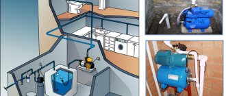
Diagram of a water supply device from a well with the inclusion of a hydraulic accumulator
Installing a hydraulic accumulator
After purchasing a suitable model of electric pump for a well or well and connecting it to the pipeline, calculating the volume and purchasing the required hydraulic tank, you need to install it correctly. If the model has a large volume and is installed on vertical legs, you should use the following recommendations:
- It is better to install a volumetric storage tank at the highest point of the house (attic, second floor) - this will create maximum pressure in the water line.
- The floor in the room must be level, humidity must not exceed established standards in order to avoid corrosion of the galvanized flange and surface of the tank.
- It is better to connect the device using a flexible pressure hose in a stainless steel braid and one-inch diameter union nuts made of brass. You should avoid supply hoses with aluminum braiding and mounting couplings made of cheap silumin, a brittle aluminum-silicon alloy.
Rice. 10 Connection diagram for a hydraulic accumulator for individual water supply systems
How to check the pressure in the accumulator
The tank must be empty during measurements.
To do this, turn off the pumping station, open the water tap and wait until the water supply stops. To measure pressure you need:
- unscrew the cap that closes the fitting with the spool located on the tank body;
- connect the pressure gauge to the spool (you can use an electronic or automobile pressure gauge), take the reading and compare it with the calculated value;
- if the pressure level decreases, pump up the compressor to the optimal value;
- To reduce pressure, bleed air.
If adjustment is carried out before the hydraulic tank is included in the system, it must be left for a day. After this time, after a control measurement, the device is installed.
Determination of tank parameters
In most cases of inclusions, hydraulic tanks for water supply are installed according to the principle: the larger the volume, the better. But too large a volume is not always justified: the hydraulic tank will take up a lot of useful space, the water will stagnate in it, and if power outages happen very rarely, there is simply no need for it. A hydraulic tank that is too small is also ineffective - if a powerful pump is used, it will turn on and off frequently and quickly fail. If a situation arises when installation space is limited or financial resources do not allow you to purchase a large-capacity storage tank, you can calculate its minimum volume using the formula below.
Rice. 6 How to correctly calculate the volume of a hydraulic tank in a water supply system
Another calculation method is to calculate the required volume of the hydraulic tank based on the power of the electric pump used.
Recently, modern high-tech electric pumps with soft start and stop, frequency control of the speed of rotation of the impellers depending on water consumption have appeared on the market. In this case, there is no need for a large-volume hydraulic tank - soft start-up and adjustment do not cause water hammer, as in systems with conventional electric pumps. Automatic control units of high-tech devices with frequency control have a built-in hydraulic tank of a very small volume, designed for its pump group.
Fig. 7 Table of calculated values of pressure and volume of the hydraulic tank depending on the operating modes of the water supply line
How to repair a pumping station: types of faults
Failure of the pump and auxiliary equipment is typical, therefore the set of problems is usually the same for all unit owners. It is better to know in advance about possible defects in order to prevent their occurrence or react quickly.
The pump does not turn off, the pressure does not increase
In this situation, the device works “idle”, that is, electricity and time are wasted, but the result is not achieved. This significantly increases wear on parts. Here are the possible reasons and their solution:
- Insufficient water in the well. If power allows, you can immerse the equipment deeper into the face.
- Clogged pipes. The pumping station will need to be cleaned, but it is better to start with the mains. But after this, it is imperative to install coarse filters. Catchers will protect against the penetration of contaminants. You can order filtration equipment on the website.
- A broken check valve - it stops coping with its main task, that is, it does not prevent the liquid from draining back into the face when the pump is not working. It can be repaired, but is often easier to replace.
- The filter itself is clogged. The reasons and solutions are the same as for clogged pipes. In fact, any element can become clogged. Often this is also the check valve of the pumping station, and since it is quite easy to clean it (just disassemble and wash), we will not make this a separate problem.
- The contacts on the relay are oxidized, which is why the circuit does not open. They just need to be cleaned, or less often, the sensor needs to be replaced.
- The impeller of the pump has naturally worn out and needs to be replaced with a new one.
- Insufficient voltage in the electrical network. The solution may be to install a stabilizer in the circuit.
The electric pump turns on too often
Perhaps the reason is as follows:
- For high flow rates, the volume of the hydraulic tank is not large enough. You can replace it or install a second, additional hydraulic accumulator.
- The relay settings are incorrect. It is necessary to tighten the springs so that the switching occurs at a pressure of 1.4 bar.
- The check valve is broken and the water is drained back into the well, so it has to be constantly pumped up.
- A torn membrane is one of the most difficult faults, since most likely the entire hydraulic tank will have to be replaced. In addition, there are additional symptoms - the pumping station is leaking (drops form near the nipple), and the pressure in the tap becomes less.
Air in water
This can be detected not by small bubbles in the flow, because this is the norm, but because the liquid comes out in jerks and not evenly. Most likely, the reason is simple - the water level in the well has decreased somewhat, so you need to lower the hose from the pump a little. But it may be that some connections in the pipeline have lost their tightness. Then air gets into the cracks. It is necessary to go over all joints with sealant.
AMETHYST - 02 M Residential building for up to 10 people or up to 2 cubic meters/day.
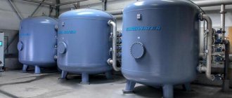
Aeration unit AS-1054 VO-90
Main table dispenser AquaPro 919H/RO (hot and cold water)
Doesn't turn on
Failure to start may be due to:
- No electricity. Check all contacts to see if voltage is supplied to the electric pump.
- If the pump itself breaks down, it needs to be repaired. And if the engine in it has burned out, it is easier to replace it with a new one.
- Oxidized contacts. They are easy enough to clean.
The electric pump hums, but does not pump water
Possible reasons:
- Unstable voltage - you can install a stabilizer.
- The terminals in the capacitor at the pumping station have burned out; they need to be checked with a tester and replaced.
- Check valve clogged. Its cleaning is carried out by disassembling the components and washing under pressure.
- The impeller is jammed. Sometimes it is enough to simply lift the hose to the surface and turn the cavities with your hands. In this case, the cause is probably a slight blockage.
Working with jerks
Pressure surges can be harmless, for example due to the appearance of an air lock in the system, or potentially dangerous, leading to further malfunctions. This could cause the relay to fail. Check the pressure gauge, if it shows values at which switching on or off should not occur, however, they alternate, which means the sensor has confused the settings. Sometimes you can fix this yourself by tightening the nuts on the large and small springs in the relay.
Another possibility, similar to an air lock, is depressurization. All connections should be checked.
Water flows unevenly
In fact, this is the same problem associated with the presence of air in the liquid. However, there may be another reason - incorrect settings on the relay, which is why the pressure is not maintained high enough.
Purpose of operation of hydraulic accumulators
Hydraulic accumulator device
To provide the house with water, submersible or surface pumps are fully used. Depending on the type of pump, the accumulator can be horizontal or vertical. How air bubbles will be removed from the water depends on the design. The choice of a suitable device will depend on the location of the pumping station and the power of the pump.
The devices differ in types and sizes, but have the same functions, namely:
- Accumulate and release hydraulic energy;
- Suppresses water hammer and pulsations;
- Contributes to the normal operation of the entire water supply system. Hydraulic accumulators are universal and for this reason are widely used in most industries. They are also used in sea, air and maritime transport.
Air in the accumulator
Due to the special design of the hydraulic accumulator tank, loads are reduced. The hydraulic tank is divided into two parts (water and air) by a membrane. The pressure in the accumulator softens the water hammer that is inevitable during plant operation. The hydraulic accumulator is also capable of maintaining pressure in the pump system.
Hydraulic accumulator device
The main components of the hydraulic tank are:
- A sealed housing, which is divided by a special membrane into two chambers - for water and for air.
- Membrane. This part of the tank stores water. The membrane is made of a special material – butyl. The latter is resistant to biological substances and is safe to use.
- Pneumatic valve. This part is designed to regulate air pressure in the system. In small tanks, a tee or tap is installed instead of a valve. What air pressure should be in the accumulator also depends on its volume (on average, 1.5-2 atm is normal).
Important! The design of the tank should be as simple as possible so that during disassembly it is not necessary to completely drain the water from the membrane.
To avoid hydraulic losses, the diameter of the pipeline and pressure pipe should be selected with great accuracy.
Purpose of hydraulic accumulators and expansion tanks
Initially, we will divide all the tanks under consideration into two main types. The first type is devices designed to compensate for excess pressure (volume) in heating devices. These are expansion tanks, or “expansion tanks” from the English word “expansion” - expansion. To imagine why expansion machines are needed, consider the operation of the heating system. When the boiler heats up, the temperature of the coolant fluid in it rises. When heated, the liquid expands. This leads to an increase in its volume by approximately 0.3% for every 10°C. Therefore, with an increase in temperature by 70°C, the initial volume of coolant will increase by approximately 3%. The liquid is practically incompressible and if the heating system is not equipped with an additional device that allows this volume to escape somewhere, its destruction will inevitably occur. To eliminate this, expansion (compensation) tanks are used. Open expansion tanks, common in the past, had a number of disadvantages and are now practically not used. Taking into account Russian engineering conservatism, we will once again describe some of the disadvantages of open expansion tanks:
- The presence of an open tank determines the increased volatility of the liquid and the need for constant replenishment;
- More expensive installation of an open tank. It must be installed at the very top of the heating system. It is necessary to provide a special place and ensure that it is insulated and prevents freezing, while a closed tank can be installed anywhere;
- Increased corrosion in the system due to access to oxygen;
- An open heating system operates at low pressure and is therefore difficult to control.
The second main type of tank is water tank (hydraulic accumulator). Their task is to accumulate a certain amount of water and release this amount under the right pressure at the right time. Like heating systems, water tanks can be open or closed. All the disadvantages listed earlier for open tanks of heating systems also apply to water tanks. But in addition, a device is needed to prevent the tank from overfilling. The appearance of expansion machines and hydraulic accumulators is shown in the figures below
Adjusting the hydraulic tank in the water heater trim
There is one peculiarity here. Such hydraulic tanks should have a slightly higher operating air pressure, namely 0.2 bar higher than what is written in the instructions.
So, if the pump produces 3.5 bar, the hydraulic tank is adjusted to 3.7 bar. The first performance check and adjustment is performed before starting the system, until the container is filled with coolant.
The absence of liquid in the chamber is normal operation. And it fills only when the water in the pipes heats up. Lack of air pressure in the expansion tank leads to the coolant filling the tank, which is a violation of operational requirements. In this case, it is necessary to turn off and drain the system, and then adjust the hydraulic tank again.
Prevention, repair and troubleshooting
Any types of hydraulic accumulators for water supply systems require comprehensive maintenance and timely prevention.
There are a huge number of reasons for the breakdown of expansion tanks, but the main ones are the high frequency of pumping equipment switching on, water supply through a check valve, low water pressure, low operating pressure in the hydraulic tank, damage to the internal membrane or outer walls of the housing, and incorrectly selected tank volume.
In order to eliminate serious breakdowns and prevent the emergency condition of the tank, regular inspections and preventative maintenance of the device are required.
Some breakdowns can be resolved as follows:
- Air pressure is increased by forcing it through the nipple hole using pumping or compressor equipment.
- The damaged surface of the membrane or housing is restored in the service center (service center). If there is serious damage, they are replaced.
- The pressure difference is equalized by significantly increasing the differential, taking into account the operating frequency of the installed pumping equipment.
- The sufficient volume of the hydraulic tank is determined before installation work begins.
To ensure uninterrupted operation of the system, there should be no air pockets in it. The frequency of inspections is once every 3 months. During this period, full control is carried out over the set pump response thresholds, relay settings, the tightness of the housing, the serviceability of the membrane and the absence of leaks.
Incorrect adjustment of any element of the system can affect the performance and durability of the hydraulic tank.
The hydraulic accumulator for hot water and cold water supply is successfully used in private households. Proper connection and configuration of the device will ensure a long service life and efficient operation of the water supply system.
Prevention of proper operation of the pumping system
Maintaining the good condition of the pumping station is created by a rubber membrane, which is constantly exposed to air and water. Rubber is an elastic, pliable material, but over time it can become deformed and the pressure in the hydraulic tank may decrease slightly. For this reason, in order for the pumping station to work properly, it is necessary to carry out a preventive check of the unit approximately once a year and monitor the air pressure in the empty tank.
If the existing pressure is slightly higher than normal, then it needs to be reduced. To reduce the pressure, you need to add air to the container using a car pump through the nipple.
Removing air pockets
Water supply systems must contain air diluted in water. Air entering the tank is released and accumulates. Because of this, air pockets form in different areas of the system.
To prevent plugs from forming, fittings with valves are built into the design of large tanks. Gas removal technology is used for vertical tanks from one hundred liters. For horizontal tanks, another pipeline assembly is used to remove air, which includes a sewer drain, ball valves and an outlet nipple. For containers up to one hundred liters, fittings and auxiliary components are not used. Gas removal and pressure regulation in hydraulic accumulators for systems of 24,50, 80 liters is done during a routine inspection of the unit when the container is empty.
Installation of a hydraulic accumulator
The selection of the device of the optimal shape depends on the characteristics of the room in which it will be installed. Designs do not give importance, but rather the dimensions of the room and the apparatus, so that they provide convenient maintenance. And also, the closer the hydraulic tank is located to the pump, the better the operation of the water supply system will be.
Since the hydraulic accumulator operates constantly, and the hydraulic tank membrane is exposed to water and air, when installing this device it is necessary to take into account the required safety margin when exposed to vibration and noise. In order to prevent destruction of the structure and the room, the unit is screwed to the floor using rubber gaskets.
And flexible adapters from the tank to the pipeline system are an integral part of it. There are special requirements for the water supply system; the system must be reliable, stable, comfortable to use and safe. That is why it is best to entrust the installation of a hydraulic accumulator to specialists.
If you install the device yourself, it may fail even due to small things. Before choosing a hydraulic accumulator, you need to focus on its volume. Because the comfortable and efficient operation of the water supply system will depend on the volume.
Volume of the tank. Calculation
To correctly calculate the volume of a hydraulic accumulator tank, it is necessary to take into account why it will be installed.
The tank can be used to prevent frequent switching on of the pumping system, to maintain pressure when the pump is turned off, also to conserve water and compensate for peak values during operation of the water supply system.
In everyday life, pumps with an average capacity of 30 liters per minute are used, and a hydraulic tank with a capacity of from fifty to eighty liters is suitable for this. But for production purposes, larger volume hydraulic accumulators are used. The air pressure in the hydraulic accumulators will have different indicators. In order to compensate for peak water consumption values, it is necessary to take into account the nature of its consumption at home or at work.
Accumulator pressure for water supply systems
Setting the pressure in the accumulator must follow the following rules:
- For a one-story house, one bar is suitable, but if the tank is installed in the basement, then another bar is added.
- The mark should be higher than at the high point of water intake.
- The pressure inside the container is calculated by the formula: to the highest point of water intake, six are added to the height of the pipes and the finished result is divided by ten.
- If there are many consumption points or there are many pipeline branches, then a little more is added to the result of the previous calculations. The number of additions is determined experimentally. If the value is underestimated, then water will be consistently delivered to the devices. And if this value is too high, then the accumulator will be empty all the time, the pressure will be strong and there may be a possibility of compromising the integrity of the membrane.
To make the pressure in the accumulator normal, the air in it is pumped up using a simple pump, and to reduce the air, the air is released a little. For this purpose, the pneumatic valve is located under a special cover. But this manipulation must be carried out when there is no water pressure; to do this, you need to close the taps. Indicators are determined by a device such as a pressure gauge, which is connected to the spool.
Adjust the pressure after the pump finishes its work. Pressure differences are ensured by opening the tap at a point located nearby.
Checking the pressure in the accumulator
Before connecting the accumulator to the system, you need to check its pressure. The setting of the pressure switch depends on this, and when the unit was transported and stored, the pressure could drop, which is why checking the pressure is mandatory. The pressure in the accumulator can be monitored using a pressure gauge, which is connected to a special input on top of the tank or below it.
For a while, you can use a car pressure gauge to control the pressure; its error is small and it is comfortable to work with. But if this pressure gauge is not available, then a regular water pressure gauge will do just fine. But such pressure gauges are not very accurate.
If necessary, the pressure in the accumulator can be increased or decreased. This is why there is a nipple, which is located on top of the tank. You can connect a bicycle or car pump through the nipple and due to them the pressure in the hydraulic tank will increase. If it needs to be reduced, then with a thin object it is necessary to bend the nipple valve, releasing air.
Optimal performance
The functioning of the water supply network and the life of the storage tank depend on several factors:
- The correct choice of the maximum and minimum pressure at which the automatic switching on of the pump is triggered.
- Correctly setting the air pressure level in the tank.
When performing independent checks and adjustments of indicators, you should follow the recommendations of specialists. The basic rule is that the air pressure in the hydraulic storage tank must be lower than the minimum pump start pressure. The difference in indicators is 10-12%. Following the recommendation allows you to save a small amount of water until the next time you turn on the unit. Example: if the pumping station automatically starts working at 2 bar, the air pressure should be 2-0.2 = "1.8" bar.
The air pressure in the storage tank does not depend on its volume. The average for containers measuring 24-150 l is 1.5 bar, 200-500 l - 2 bar. The initial factory air injection of 1.5 atmospheres in conditions of low water consumption of a one-story building can be reduced to 1 atmosphere. Low pressure in the pipes reduces wear and tear on the system, but limits the use of plumbing fixtures. Reducing the pressure to less than 1 bar will result in excessive stretching of the rubber bulb. The membrane will come into contact with the metal casing. Contact will cause accelerated wear of the rubber.
Excessive air pressure (more than 1.5 bar) is also not desirable. It will take up most of the tank, reducing the amount of water drawn. There will also be an increased load on the pipes and components of the water supply system.
Pressure calculation
To calculate the optimal air pressure in the tank, there is a formula: P=”(Hmax+6)/10,” where
- P – air pressure in atmospheres;
- Hmax is the distance to the highest point of the home water supply network.
The highest point of analysis is the shower on the top floor of the building. The distance from it to the installation site of the pressure tank is measured. The larger the gap, the higher the pressure required to lift the water. The use of numbers will add clarity to the calculation. For a building with a height of 2 floors, the Hmax value will be 7 m. The pressure will be P=”(7+6)/10=1.3″ atmospheres. For a height of 10 m, a pressure of 1.8 atmospheres is required.
Before purchasing a hydraulic accumulator, the volume of the device is calculated. Calculations take into account:
- maximum water flow;
- number of pump starts per hour;
- air pressure in the tank;
- lower and upper pressure limits for pump activation;
- coefficient related to pump power.
After installing the membrane tank, you will need to set the minimum and maximum threshold for the automation (pressure switch). The volume of water coming from the hydraulic accumulator depends on the difference between the maximum and minimum indicators. Increasing the parameter increases the efficiency of the device, but leads to rapid wear of the membrane. For private houses, a difference of 1-1.5 bar is recommended.
The minimum pressure in the membrane (Pmin) should be 10% higher than that of the air in the tank cavity. For stable operation of the system, the pressure drop must be 0.5 bar or higher. This value is taken into account when calculating Pmin. The upper response limit (Pmax) is calculated based on the characteristics of the pump - the pressure value is divided by 10. The calculated value does not correspond to the real one due to changes in the declared parameters of the unit associated with wear. It is recommended to take the upper level indicator 30% less than the pressure characteristic.
Purpose and device
In order to maintain constant pressure in the water supply system of a private house, two devices are needed - a hydraulic accumulator and a pressure switch. Both of these devices are connected to the pump through a pipeline - the pressure switch is located in the middle between the pump and the accumulator. Most often it is located in close proximity to this tank, but some models can be installed on the pump body (even submersible). Let's understand the purpose of these devices and how the system works.
A hydraulic accumulator is a container divided into two halves by an elastic bulb or membrane. In one there is air under some pressure, in the second water is pumped. The water pressure in the accumulator and the amount of water that can be pumped into it are regulated by the amount of pumped air. The more air there is, the higher the pressure is maintained in the system. But at the same time, less water can be pumped into the container. Usually it is possible to pump no more than half the volume into the container. That is, no more than 40-50 liters can be pumped into a hydraulic accumulator with a volume of 100 liters.
For normal operation of household appliances, a range of 1.4 atm - 2.8 atm is required. To maintain such a framework, a pressure switch is required. It has two response limits - upper and lower. When the lower limit is reached, the relay starts the pump, it pumps water into the accumulator, and the pressure in it (and in the system) increases. When the system pressure reaches the upper limit, the relay turns off the pump.
In a scheme with a hydraulic accumulator, water is consumed from the tank for some time. When enough has flowed out for the pressure to drop to the lower response threshold, the pump will turn on. This is how this system works.
Pressure switch device
This device consists of two parts - electric and hydraulic. The electrical part is a group of contacts that closes and opens turning the pump on/off. The hydraulic part is a membrane that exerts pressure on the metal base and springs (large and small) with the help of which the pump on/off pressure can be changed.
The hydraulic outlet is located on the back of the relay. This can be an outlet with an external thread or with an American-type nut. The second option is more convenient during installation - in the first case, you either need to look for an adapter with a union nut of a suitable size or twist the device itself, screwing it onto the thread, but this is not always possible.
The electrical inputs are also located on the back of the case, and the terminal block itself, where the wires are connected, is hidden under the cover.
Types and varieties
There are two types of water pressure switches: mechanical and electronic. Mechanical ones are much cheaper and are usually preferred, while electronic ones are mainly delivered to order.
| Name | Pressure adjustment limit | Factory settings | Manufacturer/country | Device protection class | Price |
| RDM-5 Gilex | 1- 4.6 atm | 1.4 - 2.8 atm | Gilex/Russia | IP 44 | 13-15$ |
Italtecnica РМ/5G (m) 1/4″ 1 - 5 atm 1.4 - 2.8 atm Italy IP 44 27-30$ Italtecnica РТ/12 (m) 1 - 12 atm 5 - 7 atm Italy IP 44 27- 30$ Grundfos (Condor) MDR 5-5 1.5 - 5 atm 2.8 - 4.1 atm Germany IP 54 55-75$ Italtecnica PM53W 1″ 1.5 - 5 atm
Italy
7-11 $ Genebre 3781 1/4″ 1 - 4 atm 0.4 - 2.8 atm Spain
7-13$
The difference in prices in different stores can be more than significant. Although, as usual, when buying cheap copies, there is a risk of running into a fake.
Accumulator pressure
In the air chamber of the accumulator, the pressure should be 10% lower than the pressure when the pump is turned on.
An accurate indicator of air pressure can only be measured with the tank disconnected from the water supply system and in the absence of water pressure. Air pressure must be constantly monitored and adjusted as necessary, which will increase the life of the membrane. Also, to continue the normal functioning of the membrane, a large pressure drop should not be allowed when the pump is turned on and off. A normal difference is 1.0-1.5 atm. Stronger pressure drops reduce the service life of the membrane, greatly stretching it; moreover, such pressure drops do not allow comfortable use of water.
Hydraulic accumulators can be installed in places with low humidity, not subject to flooding, so that the flange of the device can successfully serve for many years.
When choosing a brand of hydraulic accumulator, you need to pay special attention to the quality of the material from which the membrane is made, check certificates and sanitary and hygienic certificates, making sure that the hydraulic tank is intended for drinking water systems. You also need to make sure that you have spare flanges and membranes, which should be included so that in case of a problem you don’t have to buy a new hydraulic tank
The maximum pressure of the accumulator for which it is designed must be no less than the maximum pressure in the water supply system. Therefore, most devices can withstand a pressure of 10 atm.
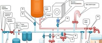
Connection diagram for hydraulic accumulator
Depending on the assigned functions, the connection diagram of the hydraulic accumulator to the water supply system may be different. The most popular connection diagrams for hydraulic accumulators are given below.
Booster pumping station wiring diagram
Such pumping stations are installed where there is high water consumption.
As a rule, one of the pumps at such stations operates constantly. At the booster pumping station, the hydraulic accumulator serves to reduce pressure surges when additional pumps are turned on and to compensate for small water withdrawals.
This scheme is also widely used when the water supply system frequently interrupts the supply of electricity to booster pumps, and the presence of water is vital. Then the water supply in the hydraulic accumulator saves the situation, playing the role of a backup source for this period.
The larger and more powerful the pumping station, and the greater the pressure it must maintain, the larger the volume of the hydraulic accumulator, which acts as a damper, must be. The buffer capacity of the hydraulic tank also depends on the volume of the required water supply, and on the difference in pressure when the pump is turned on and off.
Scheme for a submersible pump
For long-term and uninterrupted operation, the submersible pump must make from 5 to 20 starts per hour, which is indicated in its technical characteristics.
When the pressure in the water supply system drops to a minimum value, the pressure switch is automatically turned on, and when the maximum value is turned off, it is turned off. Even the most minimal water flow, especially in small water supply systems, can reduce the pressure to a minimum, which will instantly give a command to turn on the pump, because the water leakage is compensated by the pump instantly, and after a few seconds, when the water supply is replenished, the relay will turn off the pump. Thus, with minimal water consumption, the pump will run almost idle. This mode of operation adversely affects the operation of the pump and can quickly damage it. The situation can be corrected by a hydraulic accumulator, which always has the required supply of water and successfully compensates for its insignificant consumption, and also protects the pump from frequent activation.
In addition, a hydraulic accumulator connected to the circuit smoothes out a sharp increase in pressure in the system when the submersible pump is turned on.
The volume of the hydraulic tank is selected depending on the frequency of activation and power of the pump, water flow per hour and the height of its installation.
Connecting a hydraulic accumulator to a water heater
For a storage water heater in the connection diagram, the hydraulic accumulator plays the role of an expansion tank. When heated, water expands, increasing the volume in the water supply system, and since it does not have the ability to compress, the slightest increase in volume in a confined space increases the pressure and can lead to destruction of the water heater elements. The hydraulic tank will also come to the rescue here. Its volume will directly depend and increase from an increase in the volume of water in the water heater, an increase in the temperature of the heated water and an increase in the maximum permissible pressure in the water supply system.
Connecting the hydraulic accumulator to the pumping station
The hydraulic accumulator is connected in front of the booster pump along the water flow.
It is needed to protect against a sharp decrease in pressure in the water supply network when the pump is turned on. The capacity of the hydraulic accumulator for the pumping station will be greater, the more water is used in the water supply system and the smaller the difference between the upper and lower pressure scale in the water supply in front of the pump.
Recommendations for use
After the accumulator is installed, it must be properly maintained. About once a month you should check the pressure switch settings and adjust them if necessary. In addition, you need to check the condition of the housing, the integrity of the membrane and the tightness of the connections.
The most common failure in hydraulic tanks is diaphragm rupture. Constant cycles of tension and compression eventually lead to damage to this element. Sudden changes in pressure gauge readings usually indicate that the membrane has ruptured and water is entering the “air” compartment of the accumulator.
To make sure there is a breakdown, you just need to bleed all the air from the device. If water follows it from the nipple, then the membrane definitely needs to be replaced.
Fortunately, these repairs are relatively easy to make. To do this you need:
- Disconnect the hydraulic tank from the water supply and power supply.
- Unscrew the bolts that hold the neck of the device.
- Remove the damaged membrane.
- Install a new membrane.
- Reassemble the device in reverse order.
- Install and connect the hydraulic tank.
Upon completion of the repair, the pressure settings in the tank and pressure switch should be checked and adjusted. The connecting bolts must be tightened evenly to prevent the new membrane from warping and to prevent its edge from sliding inside the hydraulic tank housing.
Replacing the accumulator membrane is relatively easy, but you need to make sure that the new membrane is the same as the old one
To do this, install the bolts in the sockets, and then alternately make literally a couple of turns of the first bolt, move on to the next, etc. Then the membrane will be pressed against the body equally along the entire circumference. A common mistake made by beginners in repairing a hydraulic accumulator is the incorrect use of sealing agents.
The installation site of the membrane does not need to be treated with a sealant; on the contrary, the presence of such substances can damage it. The new membrane must be exactly the same as the old one both in volume and configuration. It is better to first disassemble the hydraulic accumulator, and then, armed with a damaged membrane as a sample, go to the store for a new element.
Optimal parameters
The main factors on which the operation of the water supply network and the service life of hydraulic equipment depend are the following:
- Correct calculation of the maximum and minimum pressure values at which the pump should turn on (off).
- Correct pressure adjustment in the receiver.
The air pre-injection pressure is 1.5 – 2 bar (depending on the tank volume). The determination of the air pressure value for operation in tandem with a specific pumping station is made based on the factory parameters of the pressure switch. The average pressure at which the pump turns on is from 1.4 to 1.8 bar. The shutdown threshold is usually in the range of 2.5 - 3 bar. The optimal air pressure should be 10-12% less than the pump activation pressure.
If these requirements are met, after turning off the hydraulic pump, a certain amount of water is guaranteed to be retained in the storage tank, sufficient to create a stable pressure until the next start of the pump.