Advantages and disadvantages of monolithic frame technology
Monolithic reinforced walls have the following advantages:
- the one-piece construction without seams is strong and reliable, it does not blow through, and temperature bridges do not form;
- a smooth, even surface allows you to begin finishing work without prior preparation;
- building construction in a short time;
- monolithic houses have an open layout;
- increased service life of reinforced concrete structures;
- complex architectural curved elements and arches are made quite easily.
Disadvantages of monolithic walls:
- low sound insulation;
- mandatory wall insulation;
- the ability of concrete to conduct vibrations.
What is the need for reinforcement?
In order to increase the strength of concrete and reduce its quantity, reinforcement is used. In theory, any material can act as reinforcement. But in practice, steel and composite are most often used.
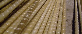
A composite is a complex of materials. The basis can be basalt or carbon fibers, which are filled with polymer. Such fittings are lightweight and not subject to corrosion.
Steel, compared to composites, has much greater strength and relatively low cost. In the process of reinforcing monolithic walls, channels, angles, I-beams, corrugated and smooth rods are used. In the case of creating complex building structures, metal mesh is used for reinforcement.
Reinforcement comes in different shapes. But most often you can find the rod one on sale. In the construction of low-rise buildings, corrugated rods are usually used. They have a low price and excellent adhesion to concrete, which makes them very popular among buyers. Steel rods, which are used in the construction of monolithic structures, usually have a diameter in the range of 12-16 mm.
Walls
How is reinforced concrete walls reinforced?
- In this case, the reinforcement frame must also be two-layer, preventing the wall from bending under load in any direction.
- The main loads will be compressive, so we will allow a minimum diameter of longitudinal reinforcement of 8 millimeters. In low-rise construction, the use of mesh made of 8 mm wire is allowed.
- The maximum pitch of longitudinal reinforcement is 20 centimeters. Transverse (horizontal) - 35 centimeters.
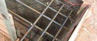
The photo shows the frame of a reinforced concrete wall with permanent formwork.
- Transverse reinforcement must have a cross-sectional area of at least 25% of the longitudinal cross-sectional area. For a diameter of longitudinal rods of 8 mm, the cross-sectional area of the transverse reinforcement will be 0.25x3.14x(8/2)^2=12.56 mm2.
- The ends of the reinforcement are anchored in the concrete (of course, without going to its surface). How it's done?
Anchoring of longitudinal reinforcement.
| A | The corrugated reinforcement itself provides sufficient adhesion to the concrete. |
| B | The C-shaped bend in the vertical plane is used for smooth rods with a diameter of up to 12 mm. |
| IN | With a larger diameter, an L-shaped bend will provide sufficient strength to tensile load. |
| G | Bending a long rod in a horizontal plane (also shown in projection 1-1) will provide the most reliable fixation of a rod of small diameter (8-10 mm). |
| D | Another option for smooth reinforcement with a diameter of 14-16 mm is welded connections with cross members of the same section. |
Nuances of reinforcement
When independently reinforcing monolithic walls, the following factors should be taken into account:
- When creating reinforcement mesh, it is best to use new steel bars because they can withstand heavy loads.
- If rust is found on new rods, do not remove it. This can lead to poor adhesion between concrete and rods.
- To cut the rods, it is best to use a grinder. If the rod needs to be bent, then the bend site is preheated immediately before the manipulation itself. But this is highly not recommended. As with welding, the material loses strength.
- If concrete has already been poured into the formwork, then reinforcement cannot be installed. If the order of work is not followed, then the whole process must be started over.
- It is also not recommended to increase the reinforcing mesh in length or height, since under heavy loads, tears may form in the areas of expansion. If such loads are not expected, then you need to perform this work as efficiently as possible.
There will be a heavy load on the walls of rooms located below ground level. Therefore, to install the mesh, you need to choose high-quality reinforcement of standard sizes, and reinforcement units for monolithic walls should be made of special wire.
Deciding on slab reinforcement
Tags: #LIRA-SAPR #ARM-SAPR #slab #reinforcement
The results of selecting slab reinforcement in LIRA CAD are shown in the form of numerical mosaics. How to adjust the colors and ranges of the mosaic, see the article.
Within the framework of this article, we will provide recommendations for making a decision on the diameter of the reinforcement in the slab.
How to design a floor slab
When designing floor slabs, a technique is often used when a reinforcing mesh with a certain combination of pitch/diameter parameters is installed over the entire area of the slab, for example, reinforcement with a diameter of 16 mm with a step of 200 mm in two directions, the symbol will look like this d16 200×200. This reinforcement mesh is also called “background reinforcement.”
The spacing of the reinforcing bars is assigned based on:
- ensuring the required reinforcement area;
- convenience of rod placement;
- possibility of concreting the structure;
The most common step for reinforcing beamless floor slabs is 200x200 mm.
The diameter of the reinforcing bars should be specified so that:
- the required reinforcement area was provided;
- the consumption of reinforcing steel was rational;
Rational consumption of reinforcing steel involves concentrating a large amount of reinforcement in places with the highest concentration of bending moments, i.e. on supports and in the span of the slab, and in the least stressed areas, the area of reinforcement can be reduced to the smallest permissible value in terms of strength and crack resistance.
Implementation of the method using an example
According to the mosaic of results, in the place where the slab rests on the column, it is necessary to install rods with a diameter of 32 mm in increments of 200 mm (s200d32), and in the span part s200d14 is sufficient, with the exception of the area between the columns, where s200d18 is required.
Attention! Simply take the background reinforcement based on the minimum result obtained, and where this area is not enough, you cannot lay additional rods. It is necessary to analyze whether these rods will differ in diameter. If there is a difference in diameter, then you need to check how a change in the reference of the center of gravity of the reinforcement will affect the operation of the slab and whether the minimum requirements for the protective layer will be violated. Based on the above, it is better not to allow discrepancies in diameters.
Method 1 - working with numbers on the reinforcement scale
We will apply the following approach: we will accept the layout of the background reinforcement with a step of 200 mm. In those places where reinforcement is required, the step is 100 mm. To ensure the required reinforcement area for the adopted layout steps, take the maximum value of the reinforcement area on the results scale and divide by two:
40.2/2=20.1 cm2.
Let's compare this value with the scale and select the diameter of the rod that will cover this area.
A rod with a diameter of 25 mm is suitable. With a layout step of 200 mm, it provides a reinforcement area of 24.5 cm2/1m. With a step of 100 mm, the area will be 24.5*2=49 cm2.
This approach saves time, but can lead to inappropriate consumption of reinforcement.
Method 2 - working with result tables
When visualizing a mosaic of results, the program, at the bottom of the window, displays the number of the element in which the maximum value of the reinforcement area is selected.
Having selected this element using a polyfilter, you need to call up the window for specifying result tables for reinforced concrete structures and create a table Reinforcement in plate elements. If some element was selected before, the result will be shown only for it.
The table contains a maximum value of reinforcement area of 36.72 cm2, which corresponds to the scale section between s200d28 and s200d32. Let's perform the same procedure as last time, but for a new area value.
36.72/2=18.36 cm2;
A rod with a diameter of 22 mm is suitable. With a layout step of 200 mm, it provides a reinforcement area of 19 cm2/1m. With a step of 100 mm, the area will be 19*2=38 cm2.
This approach, in some cases, allows you to save reinforcement.
Other methods for constructing a mesh
For greater savings on fittings, it is possible to use the following methods:
- the use of a larger pitch of background reinforcement with different pitch gradations in reinforcement zones 300/150/100;
- the use of rods of different diameters for the main mesh and reinforcement reinforcement with mandatory verification of the effect of changing the distance from the center of gravity of the reinforcement to the edge of the element;
Recommendation: when designing the mesh of the floor slab, strive not to save reinforcing steel, but to unify the rods and minimize trim.
Formwork and its installation
The construction of monolithic walls occurs using formwork. At its core, it is a form for pouring concrete mixture. The design is divided into two types:
- removable - removed after the concrete mixture has hardened;
- non-removable - is part of the wall, giving it additional qualities.
The most commonly used formwork is foamed polystyrene. It is produced in the form of blocks that are connected with locks. Expanded polystyrene insulates the concrete layer and increases sound insulation.
Installation of permanent formwork is quite simple:
- Formwork blocks are laid on the waterproofing layer of the foundation. This must be done in such a way that the reinforcement connected to the foundation passes through them. In the process of laying the first row of blocks, slopes for doors and bends of internal walls are formed.
- The second row of blocks should go through all the vertical seams of the first row. That is, the laying method is very similar to brick laying. The locks located at the bottom and top of the edges must be connected without gaps.
- The third row is the most important. It is along this that all layers of blocks are aligned.
The amount of material required is affected by the area that will be poured with concrete mixture and the thickness of the walls. The more concrete there is, the more supporting walls are needed.
In fact, the process of calculating a formwork system is not complicated. The size of the structure is calculated by dividing by the height and width of the board. For example, the average number of boards for installing 1 m3 of formwork is 40-43 pcs.
Typical sizes of polystyrene foam blocks:
- length - 1.2 m;
- width - 25 or 30 cm;
- height - 25, 30 or 40 cm;
- inner wall thickness - 5 cm;
- The thickness of the outer wall is 5 or 10 cm.
Reinforcement of monolithic walls and piers
The percentage of reinforcement from the wall section is about 10%. For this process, steel reinforcing mesh or frame is used (for increased strength).
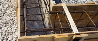
Strengthening with reinforcement is most often performed horizontally and vertically. For this, rods with a diameter of 6-8 mm are used. They are placed symmetrically near the side walls. Horizontal rods with vertical rods at opposite side walls are connected by transverse links. Such connections are needed in order to prevent buckling of vertical reinforcement. Reinforcement of the corners of a monolithic wall is mandatory. To do this, it is advisable to use U-shaped clamps. They provide the necessary fastening of the ends of the horizontal rods and protect the vertical ones from bulging.
A pier is a part of the wall between two openings (windows, doors). Reinforcement of small partitions in monolithic walls occurs using flat meshes mounted on both sides. If the floors are prefabricated, then a prefabricated frame is used. The flat walls of the first wall need to be combined with spatial frames by connecting the rods.
Methods of reinforcement and their implementation features
It is important for a novice builder to learn to understand reinforcement techniques that are selected depending on the characteristics of the structure being built, as well as the loads acting on it. According to this indicator, the following options can be used:
- Lateral reinforcement.
- Longitudinal reinforcement.
- Vertical strengthening.
Regardless of the chosen reinforcement method, preparatory operations must be carried out. They come down to preparing all the required materials, namely:
- Soft wire needed for tying reinforcement.
- Metal corners.
- Grids with cells of suitable size.
- Rectangular strips and rods.
- Steel rods.
- Paint composition for metal.
Features of the upcoming operations include the permissibility of using only one type of strengthening units. It is not advisable to use the mesh simultaneously with the rods. Let's take a closer look at what each of the methods of masonry reinforcement is. What technological features do they have?
Transverse reinforcement: function and implementation specifics
This type of strengthening is in demand in situations where there is a need to counteract transverse tensile forces during compression of the masonry. It is used in the construction of external walls, partitions, and single columns.
For this reinforcement option, separate use of building reinforcement with a diameter of 3-8 mm is allowed, and meshes that differ in the shape of the cells are:
- Square shape.
- Rectangular.
- In the form of a zigzag.
To make mesh reinforcement, in the first 2 cases, wire with a thickness of 3-8 mm is used. The pitch for the cells is taken depending on the standard size of the rod (from 3 to 12 cm).
With this type of reinforcement, the mesh is mounted every 5 rows. In a situation where building materials of larger size and weight are used - after 4 rows. To reinforce ceramic stone masonry, the mesh should be laid every 3rd row. The ends of the mesh must be brought outward by 2-3 mm to control the presence of reinforcement when laying masonry. Upon completion of the work, the protruding parts are cut off or plastered.
Important point! The size of the joining of the mesh between each other must be at least 15 cm. When reinforcing the masonry of the facing layer, at least 25 cm.
The reinforcing mesh can also be made in the form of zigzag cells, the interval between which is about 5-10 cm. Its exact value depends on the thickness of the rods, which rarely exceeds 5-8 mm. In accordance with the instructions for transverse reinforcement, the mesh is laid across 2 rows of brickwork.
Note! When calculating the amount of reinforcing mesh for work, it should be remembered that it must be at least 1% of the volume of masonry pillars or walls.
To reinforce facing brickwork, you should use mesh or reinforcement made from corrosion-resistant materials. This could be steel coated with anti-corrosion material, or a mesh made of composite reinforcement, for example basalt.
Longitudinal method of masonry reinforcement
This reinforcement option involves placing reinforcement in longitudinal seams and is most often used in earthquake-prone regions. It is designed to withstand significant lateral tensile loads during bending and eccentric compression. Used for reinforcing thin walls, partitions and pillars with great flexibility to absorb dynamic forces.
In this case, the mesh is used extremely rarely; instead, reinforcing bars with a diameter of at least 8 mm and clamps with a diameter of 3-8 mm are used.
This option for reinforcing brickwork can be done both inside a wall or column and outside. For external reinforcement, the step of the clamps is no more than 15 diameters of the longitudinal rod; for internal reinforcement, the step is no more than 25 diameters. But in both cases, the pitch of the clamps should not exceed 50 cm. At the junction of the longitudinal rods, the clamps are mounted in increments equal to 10 diameters of the reinforcement.
If a mesh made of wires 3-8 mm thick is used for reinforcement, it is laid in horizontally located seams with a pitch of about 40 cm, and is completely recessed into the seams with mortar.
Important information! For brickwork, it is recommended to use a mortar of at least M50 grade.
With internal reinforcement of brickwork, the reinforcement will be better protected from external influences. For external reinforcement, it is necessary to install a protective layer for the reinforcement. The layer thickness for walls in rooms with normal humidity is at least 15 mm, and 20 mm for walls, pillars and lintels. Outdoors or in rooms with high humidity 10 mm more, respectively 25 mm and 30 mm.
Typical sequence for reinforcement of basement walls
Strengthening the basement walls is necessary in any case and regardless of their thickness. Reinforcement of monolithic basement walls is carried out as follows:
- Buying wire with a diameter of 3 mm. Reinforcement mesh can be purchased in the form of rolls (the most common option). It is most often used for floor screeding or wall reinforcement.
- Tool preparation. Wire and wire cutters are usually sufficient. But a gun for tying reinforcement will speed up the process of tying the mesh. It has an electric motor that starts drawing the wire.
- The necessary calculations are made. Be sure to take into account the level of groundwater when calculating the thickness of the walls. If the reinforcement of a monolithic basement wall needs to be carried out below the groundwater level, then the base slab must be 20 cm thick and extend beyond the walls by 40 cm. Provided that the groundwater is far from the base, then the requirements are as follows: the thickness of the basement walls with the depth of placement 1.5-2.5 m can be from 20 to 40 cm, and the lower wall can be non-forced, and protrusion beyond the contour of the building by 10 cm is allowed.
- Cleaning the formwork. In fact, this is the removal of construction dust and dirt from the structure.
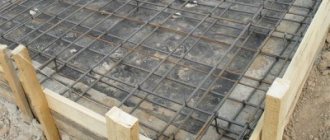
- Production of reinforcing mesh. At this point, it is important to correctly determine the cell size. For basement walls it can be in the range of 25-35 cm. Accordingly, the smaller the link, the stronger and more reliable the mesh. But cells smaller than 5 cm are not allowed, since voids may occur when pouring the concrete mixture.
- Laying reinforcing mesh into the formwork. Reinforcement with two layers of mesh will give the monolithic wall the necessary strength. It is important that the diameter of the wire is at least 12 mm, and the step both horizontally and vertically is no more than 40 cm. Both layers of the mesh must be connected in a checkerboard pattern every two cells. For connection, use a wire of the same diameter. In addition, the reinforcement and its elements should not come into contact with the walls of the formwork.
- Checking the correct installation of the reinforcing mesh. The fittings must be placed strictly vertically. Permissible deviation 1-2 mm. The reason for this is the pressure of the soil on the basement walls. The correct location can be checked with a construction or laser level.
- Pouring concrete and backfilling soil near the walls. To ensure anti-corrosion protection of the reinforcement, special solutions are added to the concrete.
TRANSVERSE REINFORCEMENT
5.18. Transverse reinforcement should be installed based on the perception of forces, as well as in order to limit the development of cracks, hold longitudinal rods in the design position and secure them from lateral buckling in any direction.
Transverse reinforcement is installed at all surfaces of reinforced concrete elements, near which longitudinal reinforcement is placed. In this case, the distances between the transverse rods at each surface of the element should be no more than 600 mm and no more than twice the width of the edge of the element. Transverse reinforcement may not be placed at the edges of thin ribs with a width of 150 mm or less, the width of which is only one longitudinal rod.
5.19. In eccentrically compressed elements, the load-bearing capacity of which at a given eccentricity of the longitudinal force is used by less than 50%, as well as in elements with flexibility < 17 (for example, column supports), where, according to calculation, compressed reinforcement is not required, and the amount of tensile reinforcement does not exceed 0, 3%, it is allowed not to install the transverse reinforcement required according to clause 5.18 along the edges parallel to the bending plane. In this case, reinforcement along the edges perpendicular to the bending plane is carried out using welded frames and meshes with a protective layer of concrete with a thickness of at least 50 mm and at least two diameters of longitudinal reinforcement.
5.20. The diameter of the transverse reinforcement (clamps) in knitted frames of eccentrically compressed elements is taken to be no less than 0.25 of the largest diameter of the longitudinal reinforcement and no less than 6 mm.
The diameter of the transverse reinforcement in knitted frames of bending elements is taken to be at least 6 mm.
5.21. In reinforced concrete elements in which the transverse force, according to calculation, cannot be absorbed only by concrete, it is necessary to provide for the installation of transverse reinforcement in increments of no more than 0.5 h
0 and no more than 300 mm.
In solid slabs, as well as in hollow-core and frequently ribbed slabs with a height of less than 300 mm and in beams (ribs) with a height of less than 150 mm in the section of the element where the transverse force, according to calculation, is perceived only by concrete, transverse reinforcement need not be installed.
In beams and ribs with a height of 150 mm or more, as well as in frequently ribbed slabs with a height of 300 mm or more, in areas of the element where the transverse force, according to the calculation, is perceived only by concrete, it is necessary to provide for the installation of transverse reinforcement in increments of no more than 0.75 h
0 and no more than 500 mm.
5.22. Bent reinforcement bars must be provided in bent elements when they are reinforced with knitted frames. Bends of rods must be carried out along an arc with a radius of at least 10 d
(Figure 5.2).
In bending elements, at the ends of bent rods, straight sections with a length of at least 0.8 lan
, taken in accordance with the instructions of clause 5.32, must be arranged, but not less than 20
d
in the tension zone and 10
d
in the compressed zone.
Crap. 5.2. Design of reinforcement bends
Straight sections of bent smooth rods should end with hooks.
The distance from the edge of the free support to the upper end of the first bend (counting from the support) should be no more than 50 mm.
The angle of inclination of the bends to the longitudinal axis of the element should be taken within the range of 30-60°. It is recommended to take an angle of 45°.
5.23. In eccentrically compressed linear elements, as well as in bending elements, if there is compressed longitudinal reinforcement required by calculation, in order to prevent buckling of the longitudinal reinforcement, transverse reinforcement should be installed with a pitch of no more than 15 d
and no more than 500 mm (
d is
the diameter of the compressed longitudinal reinforcement).
If the saturation of compressed longitudinal reinforcement installed at one of the edges of the element is more than 1.5%, transverse reinforcement should be installed in increments of no more than 10 d
and no more than 300 mm.
The distances between clamps of eccentrically compressed elements in places where working reinforcement is overlapped without welding should be no more than 10 d.
5.24. The design of clamps (transverse rods) in eccentrically compressed linear elements should be such that the longitudinal rods (at least through one) are located in places of kinks, and these kinks are located at a distance of no more than 400 mm along the width of the edge. If the edge width is no more than 400 mm and the number of longitudinal rods at this edge is no more than four, it is allowed to cover all longitudinal rods with one clamp (Drawing 5.3).
Crap. 5.3. Design of spatial reinforcement frames in compressed elements
5.25. In reinforced concrete walls, transverse rods, normal planes of the wall, are located at vertical distances of no more than 20 d
, and horizontally no more than 600 mm. Moreover, if the longitudinal reinforcement required by calculation has a saturation less than the minimum percentage of reinforcement (see Table 5.2), transverse rods can be placed at vertical distances of no more than 600 mm, and horizontal distances of no more than 1000 mm.
When the saturation of the longitudinal reinforcement of reinforced concrete walls is more than 2%, the transverse rods should be located at vertical distances of no more than 15 d
n no more than 500 mm, and horizontally no more than 400 mm and no more than 2 steps of vertical rods.
At this point d
- diameter of vertical rods.
5.26. Transverse reinforcement in slabs in the punching zone in the direction perpendicular to the sides of the design contour is installed in increments of no more than h
0/3 and no more than 300 mm.
The rods closest to the contour of the cargo area are located no closer than h
0/3 and no further than
h
0/2 from this contour.
In this case, the width of the area for placing transverse reinforcement (from the contour of the cargo area) must be at least 1.5 h
0
.
The distances between the transverse reinforcement bars in the direction parallel to the sides of the design contour take no more than 1/4 of the length of the corresponding side of the design contour.
5.27. Transverse reinforcement in the form of welded mesh of indirect reinforcement under local compression (crushing) must meet the following requirements:
a) the area of the mesh rods per unit length in one and the other direction should not differ by more than 1.5 times;
b) the mesh pitch (the distance between the meshes in the axes of the rods in the same direction) should be taken at least 60 and no more than 150 mm;
c) the dimensions of the mesh cells in the clear must be no less than 45 and no more than 100 mm;
d) the first mesh is located at a distance of 15-20 mm from the loaded surface of the element.
5.28. Transverse reinforcement designed to absorb transverse forces and torques must have a closed loop with reliable anchoring at the ends by welding or enveloping the longitudinal reinforcement, ensuring equal strength of the connections and transverse reinforcement.
Strengthening openings
Any opening is a weak point of the structure. Therefore, the perimeters of window and door openings must be additionally strengthened. If this is done incorrectly, the structure will crack and deform.
The dimensions and type of metal structures to reinforce openings are selected according to precise calculations. It is necessary to take into account all the parameters that affect the integrity of the building’s structure: wall material, number of storeys, opening size, type of foundation, roof weight.
There are several ways to reinforce openings in a monolithic wall:
- Reinforcement in one row using channels. This is a standard method that involves anchoring a metal frame to the wall. The width of the channel should be slightly larger than the width of the wall.
- Double-row reinforcement. The idea is to place two channels on the wall, which are then additionally attached and welded to metal plates.
- Strengthening with corners. Metal elements are attached to the edges of the opening. Their internal part is connected using a strip that is fixed in the wall. In such cases, the racks are tightened with pins or welded.
- Box reinforcement. Channels are welded parallel and vertically. A power I-beam serves as the upper element.
- Corner reinforcement. Used when it is necessary to strengthen non-standard openings and openings.
- Combination of methods. Depends on the design features of the openings.
Reinforcing holes in a monolithic wall is a rather complex and responsible process, especially when an opening needs to be made in a load-bearing wall. An incorrectly constructed opening can lead to a significant reduction in the reliability of the building. Therefore, it is better to carry out such processes with the help of a specialist.
Brief algorithm for strengthening openings:
- Marking the future hole and reinforcement.
- Installation of temporary supports.
- Direct reinforcement using metal profiles.
- Cutting.
Basement reinforcement
The ground floor most often has a height of 1.5 to 2.5 m. The reinforcement of the monolithic wall of the basement is as follows:
- Install permanent plastic formwork. It also serves as insulation for the walls.
- When installing the formwork, openings are laid for windows and doors, as well as metal sleeves for laying communications.
- Reinforcement must be done in the longitudinal direction of the walls. In this case, metal rods are connected to already installed vertical rods. The cross-section of the rod is at least 10 mm.
- If you have the necessary equipment and materials, it is better to pour concrete immediately. If this is not possible, then the concrete mixture is poured in layers. In the second option, each subsequent layer is poured three days after the previous one. The required hardness is achieved within 28 days.
- After final hardening, further construction work can begin.
