Swing gate drive: do-it-yourself manufacturing and installation
Today you won’t surprise anyone with self-opening or lifting gates. Automation makes life much easier for modern people. But the problem is that gates are divided into sliding and swing gates. With the latter there are much more problems and difficulties. When installing them, you cannot do without special knowledge and skills.
Let's look at what a drive for swinging gates is, how to install it yourself, and a few more interesting questions.
What to consider when deciding which gate to install
Sectional doors are quite easy to install and use. Many companies offer the installation of such gates, making all sorts of promotions, leaving leaflets with their contacts and information about services and repairs. And this is not a cheap pleasure, but still more affordable than automatic ones. As for automation for raised gates, it has a number of advantages. Here are some:
- When approaching the house or leaving the garage, you do not waste time opening and closing the gate.
- If it's raining or just very cold outside, you won't have to freeze when opening the gate. This can be done using a key fob transmitter that you have, which sends a signal to the built-in radio receiver in the gate assembly. You can immediately find yourself in the garage, where it is much warmer than outside.
- The appearance of such gates looks much more solid.
- Even fragile and weak girls can use such designs, because old metal gates are not so easy to open even for a man.
Preparing gates and mounting points
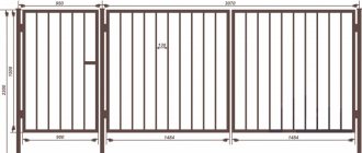
For any gates and doors, you can install a drive that automatically swings open. The main thing is to pre-design the installation of mechanics. We are talking about a strong fixation of the drive. The fastening element is steel sheets with recesses. One plate is fixed perpendicular to the sash, and the second - in a similar position only on the fence or pole.
Both sheets are installed in the same plane and at the same level. During installation, take into account the power thrust of the drive mechanism. Since it is high, welding is considered to be the best method of fastening. If the pillar is made of stone or brick, then the plate is attached to it with anchor hardware. Experts recommend laying steel elements in advance during the construction stage in such cases - it is more reliable.
A simpler installation scheme refers to the installation of doors that swing inward. A cable is laid in the gateway. For it, a plastic pipe measuring 32 mm is pre-laid.
The main parameters of the drive device can be determined at the initial installation stage. To do this, you need to measure the distance between the recesses. This is done with the gates open and closed. When the doors are open, the folded length of the mechanism is determined. The difference between the obtained parameters indicates the size of the working stroke.
Manual spring scales also help to find out the force of opening and closing doors. To do this, you need to pull the sash lock towards the opposite part. This is recommended for more accurate engine selection.
Posts and loops
The lion's share of the time in making the pillars was taken up by centering the flanges, but with the addition of corners and changing the method of fixing them, everything worked out. Thanks to the horizon created during concreting, there was no need for complex fasteners and additional washers and nuts when attaching the pillars. The parts were connected without dancing with tambourines, and “nano-deviations” from the vertical will be compensated when adjusting the hinges.
To protect the pillars at the junction with the mortgage, I used not only thick polyethylene, but also a hastily assembled gabion.
Even in the process of choosing gates, ShurickF came across an unusual hinge design that allows you to adjust all the most important parameters:
- the gap between the pillar and the sash;
- sash overhang relative to the axis of the pillars;
- the height of the valves.
Unlike conventional hinges, these make it possible to eliminate welding flaws that cannot be avoided due to lack of experience. Plus, if the pillars are skewed as a result of heaving (the swamp has become drier, but has not gone away), a small adjustment will be enough to align the position of the shutters.
The price of the issue was five thousand rubles, but “IMHO it’s worth it.” True, the position was made to order, which resulted in two weeks of downtime.
Making a drive from car window lifters
Making a homemade drive from car window lifters is quite possible. The positive aspects of this method include its silent operation and, to some extent, easy installation scheme. There is a negative point, and it lies in insufficient power traction. This is explained by the small working stroke.
To create a drive, you can use two types of window lifters, which have:
- The working mechanism is based on a gear wheel;
- The moving component is the toothed rack.
Regardless of the type, the drive elements are installed on a steel platform, which is firmly attached to the fence or post. Installation is carried out in such a way that the rail can move along a parallel plane relative to the doors and move in their direction.
The electric window lift system will have to be modified. The rack will need to be supplemented with a long rod, or the gear wheel will need to be equipped with a knee lever. The rod with the drive and the gate, as well as both halves of the knee lever, are connected to each other by hinges.
It is advisable to achieve good mobility and eliminate play as much as possible. This can be done by connecting two folded plates. The free space between them is equal to their thickness. This should include the second half of the hinge. Fixation is performed by hand or with anchor hardware.
During such work, installers are faced with one common difficulty - with the selection of an advantageous position of the mechanism, hinge fasteners and the area for attaching the rod to the doors. Most often, the installation is carried out like this: first, the gate sections are opened, and then they begin to slowly lock. At the same time, they monitor how the drive mechanism behaves.
Upon completion of successful installation, do not forget to equip the drive with a protective cover.
Automation for sliding gates
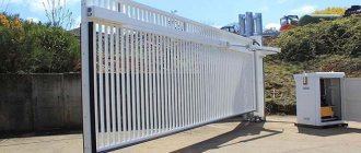
All drives for installation on sliding gates have the same design: there is a drive with a drive gear and a rack attached to the gate leaf. The rotating motor moves the rack, together with the gate. All this is controlled from the control panel located on the side. Almost all models allow you to open/close gates using remote controls. To receive their signals, you need to install an antenna and configure the remote controls (program them).
Appearance of the drive for automatic sliding gates
When choosing this type of automation, you need to pay attention to the technical parameters and additional functions.
- Power and effort. The average is 600 N/m, which is equivalent to a force of 60 kg. This is the maximum value, which does not always develop. The automation is configured so that the operation is optimal - if there is no interference, the effort is small. When overcoming obstacles that may be in the way of the sash, the force increases, sometimes to a maximum. Not everyone can resist it, and if a car or a careless person gets in the way, there will definitely be problems. Therefore, some models (recently released with 24 V power supply) provide the possibility of reprogramming. The second option is that with a certain force the sash stops or even rolls back slightly.
- Availability of temperature control. At temperatures below zero, the sash usually moves more slowly: the lubricant has thickened, and snow and ice can also interfere. With this function, the opening force automatically increases in cold weather.
- Adjustable sash speed. To make the gate produce less noise, its speed is reduced at the beginning and at the end.
- Backup power. Some modern models operating on 24 V have a built-in rechargeable battery in the body, which allows you to use the gate when the power supply is turned off. Some of them allow you to connect external backup sources.
An example of an automatic sliding gate configuration
- When choosing a sliding gate operator that operates on 230 V, you must select it depending on the intensity of use. Usage intensity is a value expressed as a percentage. It means how long this device can work without interruption. For example, for installation in a private courtyard, it is enough to choose a model with an intensity of about 30-40%. This means that out of 10 minutes, it will work in continuous mode for 3 minutes, after which it will turn off due to overheating. For collective use, for example, at the entrance to a holiday village with a population of 300 people, there should be a drive with an intensity of 70-80%.
- Availability of photocells. This is the second opportunity to ensure safety: when triggered, the movement of the valves is blocked until the obstacle disappears.
- The presence of a “wicket” mode, when turned on, the sash opens only slightly, to a distance sufficient to let a person through.
See some of the subtleties of the internal structure of drives for automatic sliding gates in the video.
Now comments to the video. The power comparison in this video is not entirely correct. There are different models for gates of different sizes and weights. The minimum threshold is 400 kg, the maximum in households is up to 1200 kg, in industrial applications more than 2000 kg. When comparing capacities, the first copy is taken from the “lightest” category - up to 400 kg, the rest are for gates of greater weight. Therefore, such a comparison is biased. Although no one says that among the little-known brands there are, and therefore cost less, there are good quality ones. Perhaps those shown in the video are like that...
About the same picture regarding gears. All drives are divided into three classes: household, semi-industrial and industrial. In household ones, the resource is the lowest and the intensity of use is the lowest - the motor will work continuously for approximately 30-40% of the total time, otherwise it will overheat and be turned off automatically (if any). This class is the cheapest, which is why the cheapest components are installed there - plastic and silumin. Not all manufacturers and not in all lines, but this is rather the rule, and in low-power household-class drives it is difficult to find gears made of steel, and especially brass. However, under normal operating conditions for this type, they work normally - they exhaust their resource, but that’s all. For this reason, you need to be thoughtful when choosing a class and monitor the service life declared by the manufacturers (available in the technical specifications).
One of the drives for cantilever gates with a bottom beam
What to indicate when purchasing
Having decided on the functions and parameters that you consider necessary, you need to look for a suitable model. When choosing in a store, sellers will ask for the following information:
- Type of supporting system (cantilever, on rail, on top beam).
- Dimensions and weight (at least approximate) of the canvas.
- Intensity of use: how many people and how often can use the device.
The seller must require all this data from you: otherwise he cannot determine the required power. equipment. If the sliding gate has already been made , you may need parameters such as the distance between the roller supports, the parameters of the foundation and the distance from it to the gate leaf. All this is necessary to correctly select the physical parameters of the drive.
Selection and calculation of engines
In order for the doors to swing open, it is rational to use various types of gear motors. If it comes to small gates, then a good option would be screwdriver motors that run on a battery, as well as washer or window lift motors. The question is different - how to make a clutch for the shaft of such an engine.
The easiest way is to contact a specialized store that sells geared motors. Consultants will help you choose a device from a wide range. In this way, you can find a mechanism with a suitable torque.
Let's imagine the following: we measured the force of closing the doors and it is equal to 13.5 kg at the level of a manual canter. 1 kg = 9.8 N. It turns out that the traction force is 132.3 N.
If we are dealing with a rack or pinion transmission, then this figure should be divided by the diameter of the wheel - this way you can find out the torque of the motor.
Before us is a “nut-screw” structure. Reduction occurs within it. Additional recalculation will be required here. Let's assume that there is an M18 stud with a 2.5 mm thread. For a single revolution, the nut makes a translational movement of 2.5 mm.
The gear ratio will then be 7.2:1. With these characteristics, the motor torque will be equal to 1.69 kg/cm.
This calculation scheme does not take into account friction, but it helps determine the permitted engine power. To compensate for energy losses in the future, it is better to ensure a power reserve of approximately 100-250%.
It is also recommended to calculate the speed of the rotating shaft. This is done like this: divide the stroke parameter by the thread size and get the number of revolutions. That is, the number of revolutions that will be needed to fully open the gate structure.
Operating folding gates
During the discussion of the design, concerns arose regarding the reliability of the foundation.
RoracottaFORUMHOUSE Member
In my opinion, the foundation for such a gate with such a lever is extremely weak. I think that after winter the pillars will collapse due to heaving of the soil.
However, everything is provided for.
ShurickFForumHouse Member
And I was afraid of heaving, which is why I made pillars on the flanges. And he left enough space for subsequent filling of the upper shelf of the brand 600x150-200 mm. The winter of 2019-2020 in St. Petersburg turned out to be simply wonderful: continuous showers instead of snowfalls and constant crossings of zero. An excellent stress test for the foundation. In the spring, the first thing I did was run with a level to check the posts: everything was fine, no deviations, the water found an easy path to the side.
If you look at the photographs, a decent area behind the gate is filled with rubble. This is one large drainage field, where the height of the fill is from 0.8 to 1.4 meters. Between the tape and crushed stone there is no more than 100 mm of black clay, which allows water to pass through perfectly. And you’re right about the lever, but in my case it’s more about the wall thickness of the pillars. Now I would make it from 4 mm. But even with 3 mm the safety margin was normal.
Next year, ShurickF planned to use the rest of the picket fence to close the openings temporarily blocked by a welded mesh with a cell of 50x50 mm. But the saying about the temporary and the permanent did not misfire here either - the green hedge grew magnificently along the grid. And the distant opening, by agreement with the neighbor, will be ennobled through joint efforts.
The gates held up perfectly the first winter, no problems. Based on the results of this winter, ShurickF will decide whether to add a concrete slab or leave it as is. What is typical is that the gabions cope with the enclosing function - when a heavy truck wheel hit, only the form with the backfill was damaged, and the post fastenings remained intact.
Stud for homemade drive
Bulky garage or country structures must be equipped with a drive with maximum traction force. Only factory mechanisms can handle this. But, you can try to create homemade devices.
The main problem is the difficulty of finding a suitable stud. Standard samples are not suitable because they are made of soft alloys. Such threads will wear out quickly. The problem can be solved by increasing the hardness of the metal and the number of threads. Let's talk more specifically about the second method.
Increasing stud threads
To create a special nut, you need to screw two or three pieces of standard hardware onto the stud. You need to do this as tightly as possible, but do not overdo it with tightening. The nuts are welded together and the joints are ground.
Don't want to do everything yourself? Then you can try to find rental hardware. They will have all the appropriate parameters. If you are lucky, you can find a trapezoidal thread profile. It is very durable. There are hardware with large pitches, which reduces the operating time of the device.
Actuator assembly
Actuator sizing
The actuator is based on a telescopic mechanism. To create it, you will need a pair of metal manifolds. One of them should fit into the other without play. Pipes with square and round cross-sections are suitable - this will not play a special role. There should be no rust, cracks or chips in the cavity. Therefore, it is recommended to purchase pipes that have not been used in work before.
The dimensions of pipes and studs should be calculated independently based on preliminary measurements.
For example, there is a folded drive 110 cm long with a working stroke of 50 cm. Then the length of the external collector should be no more than 100 cm, and another channel will be embedded inside it - even less, 80 cm.
But the length of the pin can be from 110 cm. This is influenced by the method of fixing the engine. When the gate is open, the drive pipes have an overlap of 30 cm.
Assembling the retractable part
Algorithm for assembling the retractable part:
- We pass a pin with twisted hardware through the smallest manifold and install it in the central part of the pipe. The latter should not have too large a diameter;
- Using even force, grind the hardware until it completely fits into the channel;
- We fix everything with a welding machine. There is no need to weld inside. But, if you wish, you can do this through the cut hole;
- After securing the hardware, unscrew the pin;
- At the end of the pin we fix a support part with a cleaning apparatus, which is closed on both sides;
- The bearing must slide freely along the pipe cavity. The space between it and the canal wall should be no more than 1 mm;
- We clamp the supporting element on the stud with two hardware;
- We place a couple of washers between the nuts to prevent rotation difficulties;
- Lubricate the pin with lithol;
- We insert the pin inside the smallest manifold and tighten the hardware;
To check the correct assembly, you can run a bearing along the entire length of the pipe. It should move easily and not jam.
Plugs and swivels
Now is the time to do the stub. It is a steel blank. Its size is slightly smaller than the diameter of the collector.
So that the drive can be repaired at any time, several holes should be made in the channel.
Metal strips with a hole must be attached to the end of the plug by welding. The space between them should not be greater than the thickness of the lock on the gate leaf.
Before installing the plug, 50-70 g of lithol can be placed inside the pipe. Next, install the bearing into the channel 5 cm, after which do not forget to add lubricant and plug the collector.
Actuator outer tube
The pin is completely pulled out of the manifold until the bearing rests against the nut hardware. The internal collector is installed in the external one, and the pin is tightened 5-6 turns.
After this, installers choose a method for fixing the engine. Ideally, the cylindrical motor housing is fixed inside the manifold using clamping fasteners.
If you have difficulty finding an engine of a suitable size, then you can weld a piece of channel, metal strip or corner to the rear. Thus, it will be possible to fix a small motor using any available option.
Motor installation and final assembly
The motor shaft and stud are connected together using a coupling. You can buy it in the store. It is usually sold among engine components. Sometimes you can create it yourself using a couple of small tubes. They must be nested within each other.
Re-lubricate the stud with lithol and mount the motor on the platform. Using rotational movements, it shortens the length of the trigger mechanism to its original position. Next, we lubricate the entire surface of the internal manifold with lithol and completely fold the drive mechanism.
If the engine is fixed in the inner part of the manifold, then it needs to be placed to a depth of 5-6 cm. In this case, it is advisable to use a plug identical to the first one.
The wiring can be passed through the hole made at the bottom of the collector. The main thing is that moisture does not get there. Another area to create a hole is the plug itself. Regardless of the method chosen, it is recommended to install gland entries.
When we mount the motor on the platform, we must weld the bearing to it. After this, you should definitely make sure that the structure is reliable and rigid. It is better to equip the engine with a protective casing.
When everything is done, all that remains is to install the trigger mechanisms in the required place. Finally, you need to connect the ends of the plugs with the fasteners on the doors and poles. For this you may need hardware.
Part 3
This is the third part of a video about do-it-yourself automatic swing gates. In the previous two parts, I reviewed and looked at the circuit diagram in detail. In this part you will find the device of drives and limit switches.
To open the gate, the mechanism of an ordinary VAZ jack is used, costing 500 rubles. The movable rod of this jack moves along a long screw when the handle is rotated.
Depending on the direction of rotation, the rod will move up or down. The intensity of movement determines the speed of movement of the rod. Now I will open the lid to show in detail the structure of this jack. As you can see, there is a gear inside. For our purposes, the handle and gears must be removed. To replace the lower gear with a screw, it is advisable to install a bearing of a suitable diameter. And on this side, after the screw, we will install an adapter on the gearbox shaft.
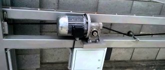
Features of gear motor
To drive the jack screw, I used the most common, simplest and cheapest windshield wiper motor gearbox from VAZ. I only use two wires - plus and minus. When the polarity changes, the gear motor changes direction of rotation.
Here is the axis of this gear motor, which we must attach to the screw.
Its shaft makes about 60 revolutions per minute. You can use other, more expensive gear motors with higher speeds. It is in this plane that these two nodes need to be joined.
For double-leaf swing gates, we will need two identical gear motors at once. I would like to warn you right away that in the domestic automotive industry, gear motors even from the same batch can have different rotation speeds. I have not yet been able to explain this paradox to myself. Please note that on this motor I have already installed two nuts.
They will somewhat strengthen the axis of this gear motor. And through them I will transfer the forces through the adapter to the top of the jack. As a result, we should have a design like this. Now I will explain how it works. I already inserted a profile square pipe with a side of 20 millimeters into the jack; a hole was drilled at the end for connection to the gate leaves. The square pipe itself is connected to the jack screw and, as it rotates, moves inward or outward.
On the other side you see a platform for mounting the gear motor. It is made in the form of a plate with holes. This is where the gear motor is attached using bolts. Its axle with nuts fits exactly into the adapter, which I made from a suitable socket wrench.
When the gear motor is turned on, rotation is transmitted through the adapter to the jack screw. The jack screw rotates and moves the square pipe I inserted outward or inward. Accordingly, this entire structure either lengthens or shortens during operation, which ensures the opening and closing of the valves. And at the same time, this design is quite rigid and strong, which is necessary for working in harsh wind conditions.
I also installed several corners on the drive housing, to which I will attach a decorative cover to protect it from atmospheric precipitation. There is a large hole drilled into the back of the drive for a pin or bolt that will secure the drive to the post.
For this design, it is better to make a small plastic cover to protect it from precipitation. The second drive is made in exactly the same way.
Features of the limit switches
And now I will tell you how the limit switches will work. These limit switches are connected to these two motors. Here you see the alarm.
Please note that here we have a plus and a minus. This minus goes right here and immediately goes to one motor, and to the second motor. That is, from here, he immediately goes at them. The second contact goes here, and goes for the first motor - here are two limit switches (connected via a diode), and for the second motor (also two diodes). They are connected differently and connected through two terminals. And it goes to the second motor, that is, this is one motor, and this one goes to the second motor. That is, they work separately.
Let's take a look now. So, we have everything on, zero voltage. Turn it on and open the gate. Now our engines are working. Our voltage is 12 volts. Now let's look. And so we look after the engines. I close the first contact - the limit switch closes only one motor. Now we look at the bottom one. I close it - it doesn't work. Now we close both - here and here. That's it, they both don't work because I shorted them both. Now I let go here, and then I let go - and they work again.
If I close the other limit switches, then nothing happens. What's here, what's here. Notice that nothing happens. Because they are spinning counterclockwise now. Now I'm stopping the scheme. I have zero here. And now I'm starting to close. They now spin clockwise. And now, in order for me to stop them, I have to close these lower ones. Closed and opened. Same thing below. We close both now - I close here, and I close here, and they both stop working.
I closed them all. Now I open them and they work again. We check the first limit switches. We close - nothing, no effect. Because there are diodes here and these diodes only pass current in one direction. Therefore, this limit switch is only for closing, and this one is only for opening. Here's the diagram.
Current limits
Now let's see how much current this circuit has. Ammeter here. We're turning it all on now. Now the engines are working, everything is blinking. And there are two and a half amps here. This whole circuit is for two and a half amperes.
Now I am stopping one contact. That is, we only have one motor spinning. The current here is 1.2 amperes.
Now I want to show the principle by which the limit switches will work. As you can see, they are installed here, here is the one limit switch, and here is the second limit switch installed.
That is, this plank – it moves. Moves here and will turn off here.
Let's see. So she went and freed this trailer.
He freed himself. Now she is heading in this direction towards this end stop. The motor is still running. Here she is approaching the end point. That's it, the engine is stopped, it doesn't turn over. And even if I press this button now, the motor does not work, does not start. Here I am, there is no effect.
Now let's try to close it. Now it is not working - we are closing it. So he went the other way. That's it, the engine no longer turns, everything has stopped. On this drive, the limit switches are located here, like this.
Here she is walking slowly. The second limit switch is here and here. Everything ends with a special fork. With a sealed fork, we can open it. Here it is completely sealed so that if anything happens, we can remove the drive completely.
This concludes my story about the miraculous transformation of ordinary gates into automatic ones with a budget of 5 thousand rubles.
Electrical connection diagram
Equipment selection
The motor can be controlled using a standard reversing circuit. But here you may encounter one nuance. Everyone knows that swing gates are equipped with a limit bar. That is why the sashes are folded in turn. When the first one comes off, the sash without the bar begins to move. But it closes last.
This is done using various methods. One of the most reliable is the use of relays with delayed switching.
The modular device consists of:
- Four contactors;
- Two time relays;
- Differential automatic;
- Power supply.
All equipment is assembled inside a plastic box. The pickup is designed to power two powerful motors.
Using a differential circuit breaker, the power is redirected to the terminals on the power supply. And a couple of DC lines are already removed on it. Each of them is responsible for powering two interconnected contactors. Their outputs are connected in parallel. From them the voltage is transmitted to the gearboxes.
Preparing to build a circuit: drawings and dimensions
To properly make and install garage doors, you need to determine the dimensions of the structure and understand the material from which it will be made.
Selecting the material
The doors of the product must be light and reliable, and therefore experts advise using sandwich panels, polycarbonate sheets or corrugated sheets. The listed materials have the following advantages:
- ease of installation;
- low cost;
- type of coating;
- light weight.
At the stage of selecting materials, you should understand the electrical mechanism that will be responsible for the operation of the product. Linear type mechanisms are perfect for small garages, as they are compact and do not take up much free space.
Tool preparation and material calculation
Having decided on the material, they are engaged in preliminary preparation of the working tool. To create an automatic gate you will need:
- screwdriver;
- brush for painting the surface of the gate;
- welding for joining metal elements;
- drill for drilling mounting holes;
- level;
- roulette;
- hammer.
You also need to determine the amount of materials:
- reinforcing bars with a diameter of one and a half centimeters;
- metal tubes with a cross section of 40 x 20 millimeters;
- iron sheets for sealing the sashes;
- two tubes with a cross section of 10 x 10 centimeters.