Most modern builders concrete a T-shaped foundation in exactly the same way as a hundred years ago: they build formwork for the supporting base (widening), pour in the mortar, and remove the formwork. Then repeat the same steps when pouring the foundation strip itself.
This time-tested algorithm is certainly good for large projects, but may not be the best way to solve the problem in small construction. You are paying a significant amount of money when you order a small amount of concrete, and small projects usually require very little. Simultaneous concreting of the support base and foundation strip allows you to order one standard batch instead of two small batches of mortar.
It should be noted that it is easier to concrete the support base and foundation strip separately. If the base is not level enough, errors can be corrected during the construction of the foundation strip. When concreting at the same time, the formwork must be constructed extremely carefully.
Rice. 1. Cast-offs and cord. The threads stretched between the cast-off boards will help to correctly position the formwork for the T-shaped foundation. First, attach a long thread, then a short one perpendicular to it, using the 3-4-5 triangle rule. Since the tensioned threads are needed only as guides, it is not necessary to place them at a certain height - it is important that they are at the same level in relation to each other.
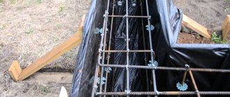
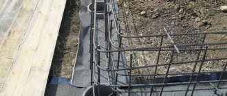
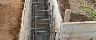
The formwork is arranged like this. First, a cast-off is installed, between which cords are pulled, determining the position of the supporting sole (Fig. 1). Then the expansion formwork is installed. The tape formwork is mounted on top using metal strips and brackets (Fig. 2).
Rice. 2. Installation of formwork for concreting a T-shaped foundation
To avoid problems
When laying the foundation of a private house, it is difficult to foresee what loads it will be subjected to in the future. Perhaps the owner will need to install a massive lathe or arrange a dance hall in the house, a water supply will break, or a powerful structure will be erected in the neighborhood, causing a rise in groundwater or a new underground flow. The loads will change, the foundation, not designed for dramatic changes in loads, will burst and sag, followed by the collapse of the building.
If the developer considers the installation of a strip foundation to be the most appropriate option, then reinforcement is necessary to guarantee its reliability. And you should know at least approximately how the foundation should be reinforced, the calculation of reinforcement, laying and tying should be done, even if other people will build your house.
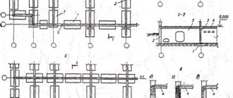
Sectional strip foundation
Calculation with reserve
Foundation reinforcement is the installation of a metal frame in its mass, designed to create a single, indestructible structure from concrete.
Making an accurate engineering calculation of the foundation of a small individual building is difficult and expensive; it requires geological surveys, comparisons with promising development projects for the area as a whole, soil and groundwater characteristics, and solving a long list of issues.
Based on this, private developers are guided by two basic rules for constructing foundations:
The base of the foundation should lie below the soil freezing depth according to the maximum indicators of the development region.
Reinforcement of the strip foundation is mandatory and is carried out in accordance with the general recommendations of the standards with a margin of safety.
Basic rules for performing reinforcement
Installation of prefabricated foundation
The construction of a T-shaped strip foundation can be done using reinforced concrete blocks. The technology for their installation is as follows:
- dig trenches below the depth of soil freezing in the region;
- their bottom is covered with a cushion of sand, which is then compacted;
- lay blocks;
- connect them together with reinforcement;
- the joints are filled with concrete, having previously installed formwork in these places;
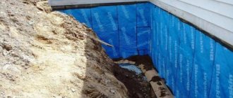
- The surface of the base is plastered, and after the applied coating has dried, it is waterproofed and insulated.
The first row of the foundation is laid out with wider blocks (or trapezoidal) compared to those located above.
The use of blocks significantly speeds up the construction process, but requires the use of lifting equipment. Due to the presence of a large number of joints, the service life of the foundation is reduced by approximately 3 times compared to monolithic analogues. The standard dimensions of the blocks determine the choice of belt parameters.
The process of constructing a T-shaped strip foundation is shown in the video below.
With fairly frequent heavy rainfall, the possibility of floods or rising groundwater, a drainage system must be installed. Its type is determined by the abundance of moisture, as well as its source. To reduce heat loss, the basement or T-shaped base is insulated in various ways.
A T-shaped foundation is a reliable foundation that you can build yourself. The choice of concrete grade is determined by the future load on the base: for the construction of lightweight structures, material marked M100 and M150 is suitable, and for heavier ones - from M200 to M400. Waterproofing the sole and tape will help extend the life of the entire building.
Arrangement of the foundation frame
The monolithic foundation is reinforced in the form of a single frame throughout its entire height. The distance between individual reinforcing bars should ensure free passage of the concrete mixture between them. In other words, if crushed stone of fraction 20-40 is used in concrete, then the gap between the frame rods should be at least 4 cm.
The use of rubble stone is much cheaper than conventional concrete mixture, but to create a unified structure, it is necessary to bandage the foundation along the entire perimeter. The reinforcement cage is incompatible with large stones; in such cases, the technological solution is to install reinforced belts at the bottom and top of the foundation.
Even the largest fractions of concrete should pass freely through the frame. On our website you can find contacts of construction companies that offer foundation design and repair services. You can communicate directly with representatives by visiting the “Low-Rise Country” exhibition of houses.
Stages of foundation reinforcement
In order for the foundation to be strong, the stages of reinforcement and installation must be strictly followed.
- The process of installing reinforcement
The degree of load on the supporting structure determines the cross-sectional size of the reinforcement necessary for installing the reinforcing belt. In places where the load will be maximum, it is desirable to install corrugated rods. - After the formwork has been installed, they begin to reinforce the foundation. Vertical rods are driven in around the entire perimeter. They almost do not take the load, but serve to attach the upper and lower belts of the reinforcing mesh to them.
- We begin the installation of horizontal rods. Don’t forget that the upper part should be 5 cm lower from the edge of the structure, and the lower part should be raised 7 cm from the bottom of the trench. In order to control the distance below, you can place bricks.
- The reinforcement can be connected in different ways: you can weld it together, overlap it, or tie it with wire. The last method is the most preferable. Firstly, it is convenient and does not require welding, and secondly, it prevents the formation of a rupture in the structure during the movement of the foundation.
Stages of work on arranging a reinforcement frame
The base for the foundation is made of a layer of sand of at least 10 cm, the sand is covered with a layer of crushed stone of fraction 2-5, then the sand-crushed stone base is compacted, and only then should the laying and tying of the reinforcement frame begin.
Reinforcing rods, cut along the length of the foundation strip on one side, are laid out at a distance of 20-30 cm from each other along the bottom of the foundation. At the corners they are screwed with soft knitting wire to the vertical rods, as well as to each other when overlapping.
To create the vertical corner supports of the frame, the horizontal bottom rods of the frame are bent at an angle of 90 degrees. Extended by overlapping joints and fastening with wire.
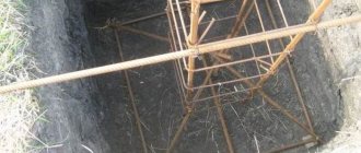
To facilitate the work on reinforcing the corners of the foundation, the installation of anchors is allowed; the work is similar to the installation of grillages or armored belts. At all corners of the foundation, 4 metal rods are driven into the ground, covered with bitumen resin on the bottom for waterproofing. They act as anchors for fastening the frame. In cross-section, the driven anchor pins should form a square with sides parallel to the foundation strip.
Anchors driven into the ground on which the frame is attached
Vertical reinforcing rods equal to the height of the foundation are screwed or tacked to the anchors for fixation. All vertical rods are tied or welded together along the perimeter, forming a pillar structure.
In order to avoid contact between the metal and the sand-crushed stone base, brick halves are placed under it along the entire length of the rod at intervals of 1 m.
Rods are cut for transverse laying of reinforcement. Their length should be 10 cm less than the width of the monolithic tape, that is, the crossbars should be completely covered with poured concrete with a distance of 5 cm from the outer wall of the foundation.
The pitch of the foundation reinforcement with transverse rods is 50 cm along the entire length of the longitudinal reinforcement.
All reinforcement connections are twisted with binding wire.
Depending on the length of the foundation side, the distance between the vertical rods ranges from 30 to 80 cm.
Only two longitudinal rows may be enough: top and bottom.
Each horizontal row is parallel to the bottom one and similar to it.
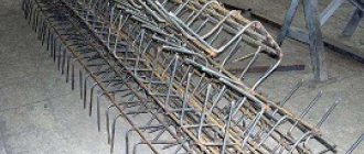
It is quite possible to assemble the frame close to the foundation, and then simply lower it into a trench or formwork.
The frame does not have to be assembled inside a hole prepared for the foundation - installation can be done outside, and then lower the entire structure down
Of course, this method is only possible if there is a flat area for assembly, otherwise it will be difficult to achieve accurate work.
This might be interesting!
In the article at the following link, read about the foundation for a house.
Fastening with binding wire
Two common methods of connecting reinforcement in a frame structure are welding and knitting, and knitting is considered more reliable. When filling a foundation with a concrete mixture, welded joints often cannot withstand the weight of the concrete.
The knitting wire, cut into 40-50 cm lengths, is doubled, inserted from below at the intersection of the rods, and twisted with pliers.
The version with twisting using a hook is simpler and faster: the wire is wound freely with a gap around the junction of the reinforcement, its ends are twisted by hand one or two turns, a hook is inserted into the gap between the reinforcement and the wire, and by turning it the wire is tightened.
Hooks are sold in hardware stores, but bending a cleaned welding electrode is sufficient for this purpose.
For large volumes of fastening reinforcement with wire, there is a special knitting gun. It is very effective in places that are easily accessible, but where access is difficult, and these are usually corner joints, a simple hook is again more useful.
Using a knitting gun significantly speeds up the process of tying foundation reinforcement. Often, plastic clamps are used instead of wire. This significantly speeds up and facilitates the work process, but at low temperatures such fasteners lose their elasticity and strength.
How fittings work
In construction, reinforcement is usually called rods of various diameters and shapes to counteract compressive and tensile loads, internal and external. The division into types, classes and groups depends on the properties and characteristics specified for the reinforcement.
The division into groups of reinforcement depends on the characteristics:
In the construction of foundations, the spatial arrangement of the reinforcement is important. Longitudinally oriented reinforcement elements work to minimize the formation of cracks by redistributing the load on the surface of longitudinally oriented structures.
Transverse reinforcement connects concrete in the compression zone with longitudinal reinforcement, redistributing and reducing loads.
Why do you need reinforcement: just a concrete beam on top, and reinforced underneath
When studying the markings of reinforcing steel, the designations C and K after the numerical value of the yield strength are of practical importance for a private developer
The C index indicates the possibility of welding the reinforcement; the absence of this index means that welding is undesirable due to the fragility of the joint. The designation K indicates the increased resistance of the reinforcement to corrosion.
This might be interesting!
In the article at the following link, read about the pile-grillage foundation.
Diagram and calculation of metal
The need for metal and estimated costs can be easily calculated if you draw a reinforcement diagram for a strip foundation with all longitudinal, transverse and vertical rods. The reinforcement is sold by weight, so when calculating, you should take into account the diameter of the reinforcement; it is possible to complete the frame with metal of different diameters and types of corrugation.
To reinforce foundations, reinforcement of various brands and diameters is used; the most common are reinforcing bars with a diameter of 10-14 mm, smooth and ribbed. For laying transverse connections, it is permissible to use round smooth reinforcement of a smaller diameter.
The most common types of reinforcement for foundations are made of steel grades M35GS and M25GS, rod lengths up to 12 m, diameter from 10 to 40 mm.
Correct selection of reinforcement cross-section is the key to foundation strength
Wire knitting patterns
Now let’s answer the question: how to properly knit reinforcement for a strip foundation? You can connect reinforcement bars using tying wire according to several schemes:
Wire tying rules
- A dead knot.
- Cross knot.
- Double-row knot.
- Tie knots of wire in the corners.
- Knitted in a bun without pulling.
In any case, you will need a special knitting device for the job. You can purchase a tying gun for rebar in specialized construction stores. A simpler device is a crochet hook. As a last resort, you can use ordinary pliers. The classic version of tying reinforcement using wire involves performing the following steps:
- Cut a wire about 30 cm long and fold it in half.
- The wire is taken in the left hand, and the knitting device is taken in the right hand.
- The wire is brought under the connection of the reinforcing bars and the hook is inserted into the wire loop.
- The rods are wrapped around the wire and its ends are placed on a hook.
- The knitting device is turned in a clockwise direction so that the ends of the wire are wound together.
- During the knitting process, the main thing is not to overtighten the wire to avoid breaking it. According to the advice of experienced craftsmen, it is enough to make three turns of the hook.
- The hook is pulled out of the loop - the connection is complete.
The entire knitting process is very labor-intensive and time-consuming, since reinforcement of strip foundations requires volumetric frames of sufficiently large dimensions.
Alternative fittings
The difficulty of transporting steel reinforcement due to its length and many problems in working with metal forced developers to pay attention to alternative solutions.
One of them could well be fiberglass reinforcement.
It has many advantages, but to appreciate them, it is worth remembering the original purpose of foundation reinforcement. In essence, the reinforcement cage should protect the concrete foundation from stretching. The modulus of elasticity of metal rods is significantly lower than that of similar plastic rods. This means that the low elasticity threshold of plastic rods will lead to deformation, and therefore destruction of the foundation, much faster than a metal one. And the meaning of replacing metal with a plastic composite disappears.
The second very unpleasant drawback concerns specifically individual developers who do not have special conditions for aligning plastic reinforcement rolled into coils.
The disadvantages of modern plastic reinforcement relate only to the undesirability of using it in monolithic strip foundations. There are many areas of application where this type of reinforcement will perform better than steel reinforcement, but not in foundations.
This might be interesting!
In the article at the following link, read about formwork for the foundation.
Correct placement of fittings
The main load of any reinforced concrete structure or slab must be withstood by longitudinal reinforcement, which is located in the lower and upper parts. Hot-rolled steel rods of class A3 are usually used as longitudinal reinforcement. When the height of the strip foundation exceeds 1.5 m, transverse and vertical rods of hot-rolled smooth reinforcement with a diameter of 6 to 8 mm of class A1 are also laid. Concrete floor slabs are also manufactured in the factory using the same principle. In this case, it is much better to make vertical and transverse reinforcement with a single clamp to create a connected solid frame. This process is explained very clearly in the video.
The longitudinal rods must be located inside the slab frame or foundation. Thanks to this bond, the likelihood of cracks appearing in concrete and their propagation is reduced, and the reinforcement bars are fixed in the required position. What should be the pitch between the longitudinal bars and transverse reinforcement bars is indicated in paragraph 7.3.4 of SNiP 52-01-2003.
Foundation reinforcement: calculation of reinforcement, laying and tying
To properly reinforce the foundation of a private house, it is necessary to calculate the reinforcement, its proper installation and tying. An incorrect calculation will lead to damage to the foundation or unnecessary costs. We will discuss the reinforcement of foundations of various structures and the principle of calculating steel reinforcement, accompanied by diagrams and summary tables.
Reinforcement of the foundation requires elaboration of the structure of the frame made of reinforcement, selection and calculation of the cross-section, length and weight of rolled profiles. Insufficient reinforcement leads to a decrease in strength and a possible violation of the integrity of the building, and its excess leads to unreasonably inflated costs for this stage.
What you need to know about fittings
When strengthening a concrete base, two types of construction reinforcement are used:
- class AI - smooth;
- class A-III - ribbed.
Smooth reinforcement is used in unloaded areas. It only forms the frame. Ribbed reinforcement, due to its developed surface, provides better adhesion to concrete. Such rods are used to compensate for the load. Therefore, the diameter of such reinforcement is, as a rule, larger than that of smooth reinforcement within the same foundation.
The diameter of the rod depends on the type of soil and the weight of the structure.
Table No. 1. Minimum standard diameters of reinforcement
If you plan to build a wooden one-story building on dense soil, you can take the tabulated values for the diameters of the reinforcement. If the house is massive and the soil is heaving, the diameters of the longitudinal reinforcement are taken in the range of 12–16 mm, in exceptional cases - up to 20 mm.
In your calculations, you will need information about reinforcement from GOST-2590–2006.
Table No. 2
Rules for reinforcing a monolithic strip foundation
When producing tape reinforcement, the following regulatory rules must be observed:
- working rods installed in the longitudinal direction of frames and meshes must have the same diameter. In the case of using reinforcement with different diameters, rods with a larger diameter must be placed in the lower zone of the tape;
- with a belt width exceeding 150 mm, the number of longitudinal working elements placed in one level should not be less than 2;
- the distance in the frame between longitudinal elements installed at the same level is not allowed to be less than 25 mm in the bottom row of the frame and less than 30 mm in the top row. When constructing spatial frames, it is also necessary to provide places for the passage of deep vibrators. In these places, the clearance should not be less than 60 mm;
- the pitch of rolled products in the strip foundation, provided for the installation of clamps or transverse elements, must be within ¾ of the height of the structure and not more than 500 mm;
- the protective layer of concrete provided for the working reinforcement of frames or meshes located at the bottom of the tape should be 35 mm when preparing with concrete, 65 mm when preparing from sand or crushed stone;
- protective concrete layer on the sides and top of the structure - 40 mm, for clamps or transverse rods - 10 mm.
Consumption of reinforcement for various types of foundation
Foundations of different designs differ in the area over which the load from the structure is distributed. For each type, the calculation of the amount of reinforcement is carried out according to its own requirements. For a correct comparison, we will calculate all foundations for the following house sizes:
- width - 6 m;
- length - 8 m;
- length of load-bearing walls - 14 m.
Calculation of reinforcement for a slab foundation
This is the most material-intensive type of foundation. There are two levels of reinforcing bars in the concrete, located 50 mm below the top and above the bottom border of the slab. The laying step depends on the perceived loads. For houses made of stone/brick, the frame cell is usually 200x200 mm. At the intersection points of the reinforcement, the upper and lower levels of the frame are connected by vertically located rods.
Reinforcement frame of a slab foundation
Let's calculate the reinforcement for our reference house (see above).
1. Horizontal reinforcement, Ø 14 mm, corrugated.
- 8000 mm / 200 mm + 1 = 41 pcs. 6 m long.
- 6000 mm / 200 mm + 1 = 31 pcs. 8 m long.
- Total: (41 pcs x 6 m + 31 pcs x 8 m) x 2 = 988 m - for both levels.
- Weight 1 linear m rod Ø 14 mm - 1.21 kg.
- Total weight - 1195.5 kg.
2. Vertical reinforcement, Ø 8 mm, smooth. For a slab thickness of 200 mm, the rod length will be 100 mm.
- Number of intersections of horizontal reinforcement: 31 x 41 = 1271 pcs.
- Total length: 0.1 m x 1271 pcs. = 127.1 m.
- Weight: 127.1 m x 0.395 kg/m = 50.2 kg.
3. Heat-treated wire Ø 1.2–1.4 mm is usually used as a knitting wire. Since the place of one connection, as a rule, is tied twice - first when laying horizontal rods, then vertical ones, the total amount of wire doubles. One connection requires approximately 0.3 m of thin wire.
- 1271 pcs. x 2 x 0.3 m = 762.6 m.
- The specific gravity of wire Ø 1.4 mm is 12.078 g/m.
- Wire weight: (762.6 m x 12.078 g/m) / 1000 = 9.21 kg.
Since thin wire can break/get lost, you need to purchase it with a reserve.
The total amount of materials for reinforcing the slab frame is given in Table No. 3.
Table No. 3
Calculation of strip foundation reinforcement
Strip foundations are reinforced concrete beams located under all load-bearing walls. It contains straight sections, corners and tees. The calculation is performed for straight sections with a small margin for strengthening corners. We assume the width of the tape is 400 mm, the depth is 700 mm.
Schematic representation of a straight section of a strip foundation
The junction of load-bearing internal and external walls
External or internal corner of external walls
The reinforcement of strip foundations is also two-level. For longitudinal sections, a class A-III rod is used, and for vertical and transverse sections (clamps), a class AI rod is used. The cross-section of the reinforcement is assumed to be slightly lower for strip foundations than for slab foundations, under the same construction conditions.
Let us calculate the reinforcement for the reference building chosen as an example (see above).
1. Horizontal longitudinal reinforcement, Ø 12 mm, corrugated. For a tape width of 400 mm, it is enough to lay two rods in each of two levels. For a wider tape, 3 rods should be laid.
- Length of all tapes: (8 m + 6 m) x 2 + 14 m = 42 m.
- Total length of reinforcement: 42 m x 4 = 168 m.
- Weight of reinforcement: 168 m x 0.888 kg = 149.2 kg.
- Taking into account the reinforcement of the corners, the mass of the rods will be 160 kg.
2. Vertical reinforcement Ø 8 mm, smooth. For a tape depth of 700 mm, the rod length will be 600 mm. The distance between the vertical rods along the length of the tape is taken to be 500 mm.
- Number of rods: 42 m / 0.5 + 1 = 85 pcs.
- Total length of rods: 85 pcs. x 0.6 m = 51 m.
- Weight of rods: 51 m x 0.395 kg/m = 20.1 kg.
3. Horizontal transverse (clamp) reinforcement Ø 6 mm, smooth. For a tape width of 400 mm, the rod length will be 300 mm. The distance between the transverse rods along the length of the tape is taken to be 500 mm.
- Number of rods: 42 m / 0.5 + 1 = 85 pcs.
- Total length of rods: 85 pcs. x 0.3 m = 25.5 m.
- Weight of rods: 25.5 m x 0.222 kg/m = 5.7 kg.
4. Knitting wire. Calculation when tying each connection with one wire Ø 1.4 mm:
- Number of nodes: 85 x 4 = 340 pcs.
- Total length: 340 pcs. x 0.3 m = 102 m.
- Total weight: (102 m x 12.078 g/m) / 1000 = 1.23 kg.
- When tying knots twice, the weight of the wire will be 2.5 kg.
The total amount of materials for reinforcing the strip frame is given in Table No. 4.
The principle of operation of reinforcement in the foundation
After the amount of reinforcement has been determined, a strip foundation reinforcement scheme must be selected, according to which the reinforced frame will be assembled. Straight sections of the structure are made of solid rods, while in corner areas additional reinforcement is required with reinforcement curved in a U or L-shape. The use of perpendicular overlap of individual reinforcement bars at corners and junctions is not permitted.
Steel reinforcement can absolutely easily withstand tensile loads 10 times greater than bare concrete.
In private construction, the most common is the strip type foundation. It works in the form of a closed contour tape made of prefabricated or monolithic reinforced concrete, which is laid under the load-bearing walls of the building and distributes the weight of the building along its entire perimeter. Strip foundations made of monolithic reinforced concrete are more common.
During operation, the foundation is subject to various loads arising from the weight of the building itself, from frost heaving and from soil movement. Under house pressure, the lower part has a tensile load, and the upper part has a compressive load. We should not forget about the forces of frost heaving, whose lifting force can significantly exceed the weight of the building and provoke tension in the upper parts of the strip foundation.
In the era of Peter I, the term “reinforcement” meant army weapons. Today we call it “weaponizing” a concrete foundation with steel rods.
The meaning of reinforcement
A strip shallow foundation must be reinforced in order to compensate for the loads acting on it during operation. Concrete has great compressive strength, but tensile or shear loads that cause concrete to move can easily compromise its structural integrity. The resistance of concrete to tension is 50 times lower than to compression.
A reinforced strip foundation is a monolithic reinforced concrete frame made of securely connected beams, which rests freely on an elastic foundation. The soil beneath the foundation is not a fixed, monolithic platform; most often it is a heterogeneous structure that is affected by movement, moisture, groundwater, the influence of snow and vegetation, air temperature, etc.
Layout of a strip foundation.
Steel reinforcement can easily, absolutely without destruction, withstand tensile loads 10 times greater than bare concrete. Steel tends to elongate without breaking when exposed to tensile loads from 4 to 25 mm (while concrete only 0.2-0.4 mm). Concrete bears compression loads better.
Combined in one material, reinforced concrete, concrete and steel make it possible to better tolerate complex tensile and compressive loads. The part equidistant from the lower and upper parts of the strip foundation actually does not take the load. This suggests that the use of a middle layer of longitudinal elements, which is often installed “for greater strength,” is unnecessary. If you are building a buried foundation (underground wall), then it must be reinforced as a monolithic concrete wall.
There are cases in independent dacha construction when builders work like this: they only reinforce the lower part of the foundation. This is argued by the fact that the load from the building will not allow the beam to bend upward, thereby creating tension in its upper part, in which it is possible to “save”.
But such unfortunate builders do not take into account the considerable lifting force of the wet, expanding soil or the force of frost heaving when water freezes in the soil. The load from these forces can be greater than the load from the structure and will cause tension in the upper portions of the foundation, which will result in the destruction of its structural integrity.
https://youtu.be/_xKAqYFUG-U
If the strip foundation is improperly reinforced, its destruction may occur, which will lead to the destruction of the walls and the entire building.
Types of material
In Russia, class A-III (A400) reinforcement of a periodic profile is used to reinforce a monolithic strip foundation. This reinforcement is presented in the form of steel round profiles with a pair of longitudinal ribs and transverse projections that run along a three-way helical line. Periodic profiles are designed for more reliable adhesion of concrete to reinforcement, which differs from a material with a smooth profile, which is more suitable for use as a strapping (clamp) of longitudinal elements.
The marking of steel reinforcement A400 indicates the yield strength of this class (390 N/mm2). But such fittings are now considered obsolete. In the early 90s, European countries switched to one class that can be boiled, the yield strength of which is 500 N/mm2. By using class A500C instead of the outdated class A400, you save over 10% of steel in construction.
We invite you to read: Do-it-yourself foundation reinforcement: a step-by-step guide
Scheme of a slab foundation for a cottage using reinforcement.
Periodic profile reinforcement of class A-III is produced in a domestic version with protrusions in the form of rings and in a “Europrofile” version with protrusions in the form of sickles. The domestically produced ring profile works to increase the adhesion strength of concrete to reinforcement, and sickle-shaped profiles increase resistance to frequently repeated loads.
Reinforcement grade A400 (A-III) is not recommended to be welded to connect rods. If steel is boiled, that is, exposed locally to high temperatures, significant structural weakening of the steel occurs. These changes in steel rods occur in the area that is being welded and in adjacent areas over a length that is equal to four diameters of the rod in both directions.
If you want to weld the connection between the rods, then you should choose special classes designed for this, which can be recognized by the letter “C” in the name: A400C, A500C. They can be boiled to connect the rods into a frame. If you do not know what class of reinforcement you have, but you need to weld the junction of the longitudinal rods, then the reinforcement must first be heated to 200 degrees Celsius in order to minimize the loss of steel strength. The length of the weld must be at least equal to 10 diameters of one rod of the reinforcement being welded (45-55% of the length of the rod).
Mesh welding
Individual mesh rods of a reinforced concrete foundation can be welded using two types of electric resistance welding: butt and spot welding.
Resistance spot welding is based on the use of heat that is generated at the points of contact of the rods during the passage of electric current to heat the metal in these areas to the melting point. By pushing the heated rods towards each other, they are securely connected. Resistance spot welding can be used to weld frame and mesh assemblies, which are two or three intersecting rods at angles of 60 and 90 degrees.
Knitting rods
Foundation design diagram.
It is also necessary to bend reinforcement to make connecting elements that work in tension (claw or standard hook) and to reinforce joints and corners. Some builders reinforce the junctions of strips and corners of strip foundations using crossbar reinforcement.
Class A-III bends in a cold state at a right angle along the bending diameter without loss of strength. If you bend the reinforcement 180 degrees, the strength will decrease by 10%. Today there are at least two very common and unacceptable methods of bending rods. Unscrupulous workers, who do not want to do extra work, either file down the point where the rod will be bent using an angle cutting machine, or heat the bend with a blowtorch (autogen or on a fire).
Scheme for calculating reinforcement for the foundation.
Reinforcement A-III (A400) is used for transverse and longitudinal reinforcement of the foundation. For additional (auxiliary) transverse reinforcement (clamps), you can also use smooth hot-rolled rod reinforcement of class A-I (A240) or A-II.
You can also use structural reinforcement to reinforce the foundation, which is installed to absorb unexpected forces (for example, forces from temperature deformations or shrinkage of concrete). If possible, reinforcement should be installed in spatial or enlarged pre-prepared elements, while reducing the amount of use of individual rods. Dirt, dust, debris, ice and snow must be removed from the concrete pad (preparation) at the site where the rods are installed.
Surface
The rods must be degreased and cleaned of all non-metallic coatings using a wire brush. An epoxy coating on the reinforcement is allowed. It significantly reduces adhesion to the concrete surface, but also increases resistance to the corrosion process.
It is allowed to have non-flaking rust on the reinforcement bars. By the way, ordinary non-flaking rust even enhances the adhesion strength of the concrete surface to the reinforcement.
Strip foundation reinforcement
Reinforcement of a strip foundation significantly increases its strength characteristics and allows you to create stable structures while reducing weight.
Strip foundation reinforcement
Calculations of reinforcement and reinforcement schemes are carried out in accordance with the provisions of the current SNiP 52-01-2003. The document has detailed requirements for calculations, provides footnotes to regulatory documents and codes of practice.
SP 63.13330.2012 Concrete and reinforced concrete structures. Basic provisions. Updated version of SNiP 52-01-2003. File for download
The strip foundation must meet the requirements for durability, reliability, resistance to various climatic factors and mechanical loads.
Reinforcement of strip foundations - work technology
The number of reinforcement elements must be calculated based on the size of the base. For foundations whose width is 40 cm, 4 longitudinal rods are sufficient - two at the top and two at the bottom. To install a row of frames in a strip base measuring 6x6 m, you will need, on average, 24 m of reinforcement. If you lay 4 rods at a time, you will need 96 m of longitudinal rods.
For transverse and vertical reinforcement of a foundation, the width of which is 0.3 m and the height of 1.9 m for each fastening at a distance of 5 cm from the surface, according to the concrete calculator, you need (30-5-5)x2 (190-5-5)x2= 400 cm or 4 m of smooth shaped reinforcement elements.
If the installation step of the clamps is 0.5 m, the number of connections will be: 24/0.5 1=49 pcs. This means, based on the calculations, you will need 4x49 = 196 m of transverse and vertical rods.
| Diameter of fittings, mm | Calculated area of the transverse rod, mm2, with the number of rods | Theoretical weight of 1 m length of reinforcement, kg | ||||||||
| 1 | 2 | 3 | 4 | 5 | 6 | 7 | 8 | 9 | ||
| 6 | 28,3 | 57 | 85 | 113 | 141 | 170 | 198 | 226 | 254 | 0,222 |
| 8 | 50,3 | 101 | 151 | 201 | 251 | 302 | 352 | 402 | 453 | 0,395 |
| 10 | 78,5 | 157 | 236 | 314 | 393 | 471 | 550 | 628 | 707 | 0,617 |
| 12 | 113,1 | 226 | 339 | 452 | 565 | 679 | 792 | 905 | 1018 | 0,888 |
| 14 | 153,9 | 308 | 462 | 616 | 769 | 923 | 1077 | 1231 | 1385 | 1,208 |
The minimum area of foundation reinforcement is regulated by regulatory documents, and the strength of the foundation depends on this
To do this, take a square or rectangle as a basis.
Before installing the frame, a sand cushion 1 m deep must be laid on the bottom of the trench.
The frame is installed as follows:
- bricks are laid at the bottom of the trench, the height of which is 5 cm (in order to create a gap between the lower part of the base and the frame);
- to install rack rods, it is necessary to make a sample in advance, according to which the rods will be cut;
- longitudinally shaped rods are laid on the bricks;
- Horizontal jumpers with a length slightly less than the thickness of the base (approximately 5 cm on each side) are tied to the longitudinal rods in increments of 50 cm using knitting wire;
- rods are attached vertically to the corners of the formed cells, 10 cm long less than the height of the base;
- the upper longitudinal rods are mounted to the vertical reinforcement;
- The upper transverse rods are tied to the resulting corners.
When reinforcing a strip foundation, it is necessary to adhere to the requirements of SNiP 52-01-2003
The main task of the foundation is to transfer the load of the building (structure) to the ground. It is obvious that the concrete in the foundation will experience an internal compression force - the walls press from above, and the soil pushes from below. Concrete, unlike reinforcement, works very well under compression. So why is reinforcement used in a strip foundation?
During the operation of a building, settlement inevitably occurs. The soil under the base of the foundation is compacted under pressure from above. The higher the pressure, the stronger the compaction occurs. If it is strictly uniform along the entire length of the strip foundation, dangerous internal forces do not arise in the foundation.
In practice, this situation occurs extremely rarely. Non-symmetry of shapes and loads causes uneven pressure. In order to reduce uneven settlement within the same building, foundation strips of different widths are usually used. More load - more width. But even in this case, it is impossible to completely equalize the pressure values under the base of the foundation.
In addition, one cannot guarantee the absolute ideality of the foundation base (soil). Various inclusions in the soil mass also form uneven sediment. Uneven humidity also has a negative impact. Leakage of water-carrying communications, lack of a blind area on one side, the likelihood of various extensions appearing (additional load leads to additional settlement) - all this creates uneven settlement.
Relatively speaking, the soil surface under the foundation strip tends to become “curved” in the vertical direction. The most dangerous areas are corners, as well as places with significant differences in loads (for example, with variable number of floors, the presence of columns, additionally loaded pylons, etc.).
We suggest you read: At what minimum temperature can a foundation be poured?
Based on material, reinforcement is divided into two types - steel and composite. The latter appeared relatively recently and, having a number of disadvantages (as well as advantages), is rarely used in private construction today.
Steel reinforcement is divided into rod and wire. To reinforce a strip foundation, bar reinforcement of a periodic profile is used as the main one (working, also called “longitudinal”) and smooth reinforcement as an additional one (transverse).
The working reinforcement must have good adhesion to the concrete to ensure joint work. Such reinforcement is made with a periodic profile, dividing it into strength classes. According to GOST of the times of the USSR, class A-III reinforcement or its equivalent according to modern GOST - A400 is used for private construction.
Periodic profile fittings.
Smooth profile fittings.
Due to some unpredictability of the degree of uneven settlement, an accurate calculation of the required diameter for a strip foundation is hardly possible. Therefore, over decades of construction and operation of buildings, design requirements for the reinforcement of strip foundations have been developed.
- The diameter of the working rods is taken to be at least 12mm.
- Working (longitudinal) rods are combined into spatial frames using transverse reinforcement by welding or knitting.
- The number of longitudinal rods in the frame is at least four (usually six).
- The transverse reinforcement pitch is assigned in the range of 200-600mm. The diameter of the rods is 6-8mm.
- The thickness of the strip foundation is usually taken to be 300mm.
- Weak spots in corners and T-shaped intersections are reinforced with reinforcing haunches or tabs. Their diameter is assumed to be equal to the diameter of the longitudinal rods.
Let's consider the reinforcement scheme for a strip foundation using the example of a one-story house with an attic measuring 10x6m in plan.
An example of strip foundation reinforcement.
Longitudinal reinforcement is made with six reinforcement bars of class A-III with a diameter of 12 mm. Transverse - with clamps made of class AI reinforcement with a diameter of 8 mm. The spacing of the clamps is 200mm in the area of corners and T-shaped intersections, and 600mm in other places.
The corners and places of T-shaped intersections are reinforced with corner and diagonal haunches made from class A-III reinforcing bars with a diameter of 12 mm. The overlap of the haunches in the area adjacent to the longitudinal rods is assumed to be 50 diameters (50x12mm=600mm).
In this case, joining along the length of the working reinforcement rods can be done with an overlap along the length of an identical length (600 mm). In such places it is also advisable to install clamps with a rapid pitch (200mm). The length of the reinforcing bars reaches 11.7 m. If possible, in order to reduce the amount of work, longitudinal connections should be avoided.
Reinforcement of corners and T-shaped intersections can also be done with so-called tabs. They represent an L-shaped bend of the longitudinal rods by the same amount of 50d.
An example of reinforcing the corner of a strip foundation with claws.
When reinforcing strip foundations, the requirements for a protective layer of reinforcement must be met to avoid rusting. For foundations, the protective layer is 40 mm at the side and top edges. For the sole, it is also allowed to take 40mm in the case of a preparation device made of concrete class. B2.5...B10 100mm thick. Otherwise, the protective layer for the sole will have to be increased to 70mm.
An important issue before starting construction is its cost. It is impossible to determine it in the volume of the foundation without determining the required amount of reinforcement. But for an initial assessment, you can use the reinforcement weight coefficient. Over decades of design and construction, an indicator of the amount of reinforcement for low-rise buildings was derived.
It is approximately 80 kg/m3. That is, if your strip foundation requires 20 m3 of concrete, on average you will need 20x80 = 1600 kg of reinforcement. It is not difficult to calculate the required volume of concrete - you just need to know the perimeter of the building, the length of the load-bearing internal walls, set the height of the tape to 300 mm and multiply by its width.
In conditions of economy, before purchasing fittings, it is advisable to perform a more accurate calculation. To do this, you will have to draw a reinforcement diagram, determine the overall molding of the longitudinal and transverse reinforcement, add 5-10% to the scraps and then multiply the obtained data by the weight of a linear meter for each diameter.
Weight table 1 m.p. reinforcing bar depending on diameter
Reinforcing bars are combined into frames by welding or knitting. Each method has its own advantages and disadvantages. The main disadvantage of a welded joint is the inability (according to current norms and standards) to make a high-quality transverse connection with a hand electrode.
Welded reinforcement frame.
In factory conditions, frames and meshes are welded by contact, rather than arc, welding. In practice, builders often neglect the requirements of the standards and cook by hand. As a result, either lack of fusion (the connection is not strong enough) or undercut (weakening of the longitudinal rod) often occurs. In addition, class A-III reinforcement can be made from steel grade 35GS, which has weldability problems.
The knitted connection is made using a knitting wire with a diameter of 0.8-3mm.
A crochet hook is used as a tool. (See photo at the beginning of the work.) The advantages of such a connection are the absence of all the disadvantages characteristic of a welded connection, but there are also some of their own - high labor intensity, less rigidity in comparison with the welded version (eliminated by means of additional diagonal spacer rods to give the frame rigidity at concreting stage).
Requirements for fittings
During the reinforcement of strip foundations, the type and controlled values of the quality of the reinforcement are established. The standards allow for the use of hot-rolled construction reinforcement of periodic profile, heat-treated reinforcement or mechanically strengthened reinforcement.
The class of reinforcement is selected taking into account the guaranteed value of the yield strength at maximum loads. In addition to tensile characteristics, ductility, corrosion resistance, weldability, resistance to negative temperatures, relaxation resistance and permissible elongation before the onset of destructive processes are standardized.
Table of reinforcement classes and steel grades
The calculation of the strip foundation is carried out in accordance with the recommendations of GOST 27751, the indicators of limiting loaded states are calculated by group.
The first group includes conditions that lead to complete unsuitability of the foundation, the second group includes conditions that lead to partial loss of stability, complicating the normal and safe operation of buildings. According to the maximum permissible states of the second group, the following are produced:
- calculations for the appearance of primary cracks on the surface of a strip foundation;
- calculations based on the time period of increase in cracks formed in concrete structures;
- calculations of linear deformations of strip foundations.
The main indicators for resistance to deformation and strength of building reinforcement include maximum tensile or compressive strength, determined in laboratory conditions on special test benches. The technology and test methods are prescribed in state standards. In some cases, the manufacturer may use regulatory and technical documentation developed by the enterprise. At the same time, regulatory and technical documentation must be approved by regulatory authorities.
For concrete structures, these values may be limited by the maximum rates of change in concrete linearity. Actual diagrams of the state of reinforcement under short-term one-sided exposure to design standard loads are taken as generalized indicators. The nature of the state diagrams of building reinforcement is established taking into account its specific type and brand. During the engineering calculation of a reinforced foundation, the state diagram is determined after replacing the standard indicators with actual ones.
Simplified calculation of strip foundation reinforcement
A simplified calculation of rolled steel for a strip foundation consists of selecting the number of working rods, as well as their diameter according to the main indicator - the minimum percentage of reinforcement.
According to the requirements of clause 5.11 Table 5.2 of the Manual to SP 52-101-2003, the total area of working rods that can absorb tensile forces should not be less than 0.1% of the cross-sectional area of the reinforced concrete structure being calculated.
Since a monolithic tape has the form of a beam, which is subject to multidirectional forces, stretched zones can be at the top and bottom of its cross section.
Thus, the main condition for the calculation is the presence in both zones of the cross-section of the structure of longitudinal working rods with a total area of at least 0.1% of the total cross-sectional area.
Let us show with an example how to calculate the diameter of rods that can be used as working reinforcement for a monolithic tape.
Formula for calculating the percentage of reinforcement according to clause 5.11 of the Manual to SP 52-101-2003: $$\quicklatex{size=25}\boxed{\mu_s = \frac{A_s}{b \times h_0} \times Pr }$$
where: Pr – unit equal to 100%;
As; – the required total area of the working rods, mm2;
b – tape width, mm;
h0; – working height of the cross section, in mm.
From this formula you can find the required minimum area of the rods: $$\quicklatex{size=25}\boxed{As = b \times h_0 \times 0.001}$$
When making calculations, it is necessary to take into account the rules for reinforcing strip foundations set out in the Manual to SP 52-101-2003 in the “Guide to the design of concrete and reinforced concrete structures made of heavy concrete (without prestressing)”.
According to clause 5.17 of the Manual to SP 52-101-2003, the minimum diameter of each of the working rods is limited to 12 mm.
Initial data: monolithic strip foundation for external walls with a section of 600 mm (b - width) by 500 mm (H - total height);
First, we determine h0, which will be equal to the height of the section without a protective concrete layer.
The protective layer that must be maintained for the lower rods on the sole of the tape laid on sand or crushed stone preparation is 70 mm. But for the upper reinforcement the protective layer is 30 mm, so we take the average value of 50 mm:
h0 = H – 50 = 500 – 50 = 450 mm
We determine the cross-sectional area of the tape that will be used in the calculations:
b x h0 = 600 x 450 = 270,000 mm2
The required minimum area of working rods As in each section zone will be equal to:
As = b x h0 x 0.001 = 270,000 x 0.001 = 270 mm2
To select the diameters of the working rods and their number according to the minimum required area, we provide Table 1.
Using the table, we find the closest values for a minimum diameter of 12 mm, provided that 3 rods are installed. The value will be between columns with 2 (226 mm2) and 3 rods (339 mm2), we take the larger one - 339 mm2 for 3 rods.
As a result, we finally accept 3 working rods each having a diameter of 12 mm in both cross-sectional zones.
Reinforcement requirements
Reinforcement cage - photo
- Requirements for the dimensions of reinforced concrete structures. The geometric dimensions of the foundation should not interfere with the correct spatial placement of reinforcement.
- The protective layer must provide joint resistance to the loads of reinforcement and concrete, protect against the influence of the external environment and ensure the stability of the structure.
- The minimum distance between individual reinforcement bars should guarantee its joint work with concrete, allow for correct joining and ensure correct technological pouring of concrete.
Reinforced strip foundation diagram
For reinforcement, only high-quality reinforcement can be used; mesh knitting is carried out taking into account the calculated design parameters. Deviations from the values cannot exceed the tolerance fields regulated by SNiP 3.03.01. Special construction measures must ensure reliable fixation of the reinforcing mesh in accordance with existing rules.
Reinforcement frame for strip foundation
SNiP 3.03.01-87. Load-bearing and enclosing structures. Building regulations. File for download
When bending reinforcement, you need to use special devices; the minimum bending radius depends on the diameter and specific physical characteristics of the building reinforcement.
The reinforcement is inserted into the formwork; the manufacture of the formwork should be carried out taking into account the requirements of GOST 25781 and GOST 23478.
STEEL MOLDS FOR THE PRODUCTION OF REINFORCED CONCRETE PRODUCTS. Technical conditions. File for download
Formwork for the construction of monolithic concrete and reinforced concrete structures. Classification and general technical requirements
Other methods of connecting reinforcement
Tying reinforcement is considered the most reliable way to connect reinforcement bars when creating a frame for a strip foundation. However, there are other options for mounting a metal skeleton:
- Using welding equipment. Having a welding machine in your arsenal and some skills in working with it, you can quickly and easily create a frame for a foundation from metal rods. But in this case, it is worth taking into account the features of such a reinforcement connection. First, welding thins the metal, making it more brittle. Secondly, the welded frame will be reliable only if the metal and electrodes are correctly selected, and all norms and rules are followed.
- Overlapping connection. This method involves not a transverse, but a longitudinal connection of the rods. In this case, individual ends of the reinforcement have an outlet of at least 15 cm for subsequent winding with wire.
- Using plastic band clamps. This method can be used when building foundations for small structures. Connecting with plastic clamps makes the knitting process somewhat easier. However, it is worth remembering that such a frame is less resistant to loads, and under the influence of low temperatures the plastic may burst.
- Using clamps or brackets made of plastic or steel.