Selection by power and methods of connecting radiators
The number of sections or the size of a panel radiator is selected based on the amount of heat required to heat the room. We have already determined this value at the very beginning; it remains to reveal a couple of nuances. The fact is that the manufacturer indicates the heat transfer of the section for a temperature difference between the coolant and the air in the room equal to 70 °C. To do this, the water in the battery must warm up to at least 90 ° C, which happens very rarely.
It turns out that the real thermal power of the device will be significantly lower than that indicated in the passport, because usually the temperature in the boiler is maintained at 60-70 ° C on the coldest days. Accordingly, for proper heating of the premises, the installation of radiators with at least one and a half heat transfer margin is required. For example, when a room needs 2 kW of heat, you must take heating devices with a capacity of at least 2 x 1.5 = 3 kW.
Indoors, batteries are placed in places of greatest heat loss - under windows or near blank external walls. In this case, connection to highways can be done in several ways:
- lateral one-sided;
- diagonal scalene;
- lower - if the radiator has appropriate pipes.
The lateral connection of the device on one side is most often used when connecting it to risers, and the diagonal connection to horizontally laid highways. These 2 methods allow you to effectively use the entire surface of the battery, which will heat evenly.
When a single-pipe heating system is installed, the lower versatile connection is also used. But then the efficiency of the device decreases, and hence the heat transfer. The difference in surface heating is illustrated in the figure:
There are models of radiators where the design provides for connection of pipes from below. Such devices have internal wiring and, in fact, they have a one-sided side circuit. This can be clearly seen in the figure, where the battery is shown in section.
A lot of useful information on the issue of choosing heating devices can be found by watching the video:
Protecting the system from air
Theoretically, air should not enter a closed heating system, but in fact it is still present there. Its accumulation is observed when pipes and batteries are filled with water. The second reason may be depressurization of joints.
As a result of the appearance of air pockets, the heat transfer of the system decreases. To combat this phenomenon, the system includes special valves and air bleed valves.
If air does not accumulate in the system, the air vent float blocks the exhaust valve. When an air lock accumulates in the float chamber, the float stops holding the outlet valve, causing air to escape outside the device
To minimize the likelihood of air pockets, certain rules must be followed when filling a closed system:
- Supply water from the bottom to the top. To do this, lay the pipes so that the water and the released air move in the same direction.
- Leave the air vent valves open and the water drain valves closed. Thus, with a gradual rise in coolant, air will escape through open air vents.
- Close the vent valve as soon as water starts flowing through it. Continue the process smoothly until the circuit is completely filled with coolant.
- Start the pump.
If the heating circuit has aluminum radiators, then air vents are required on each one. Aluminum, in contact with the coolant, provokes a chemical reaction accompanied by the release of oxygen. In partially bimetallic radiators the problem is the same, but much less air is produced.
An automatic air vent is installed at the top point. This requirement is explained by the fact that air bubbles in liquid substances always rush upward through the pipe, where they are collected by a device for removing air
In 100% bimetallic radiators, the coolant does not come into contact with aluminum, but professionals insist on the presence of an air vent in this case too. The specific design of steel panel radiators is already equipped with air bleed valves during the production process.
On old cast iron radiators, air is removed using a ball valve; other devices are ineffective here.
Critical points in the heating circuit are pipe bends and the highest points of the system, so air exhaust devices are installed in these places. In a closed circuit, Mayevsky valves or automatic float valves are used, which allow air to be vented without human intervention.
The body of this device contains a polypropylene float connected through a rocker arm to a spool. As the float chamber fills with air, the float lowers and, upon reaching the bottom position, opens the valve through which the air escapes.
Water enters the volume freed from gas, the float rushes up and closes the spool. To prevent debris from getting inside the latter, it is covered with a protective cap.
The body of both manual and automatic air vents is made of high-quality material that is not susceptible to corrosion. To remove the air lock, turn the cone counterclockwise and release the air until the hissing stops.
There are modifications where this process takes place differently, but the principle is the same: the float is in the lower position - gas is released; the float is raised - the valve is closed, air accumulates. The cycle repeats automatically and does not require human presence.
Single-circuit or double-circuit: which heating is better?
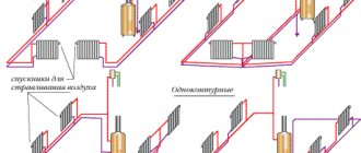
As noted above, the advantages of a single-circuit heating installation are ease of installation and reduced costs for system components, especially if we consider the option with natural circulation, which also saves energy. This option is available for installing the system in country cottages in the most remote settlements of the country, where power outages are possible.
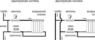
The disadvantages of single-circuit heating include uneven distribution of heat throughout the rooms; in the one that is closest to the boiler, the temperature will always be higher, since, as it passes through the main line, the coolant loses its temperature indicators.
In the case of dual-circuit heating, the coolant is distributed evenly across all radiators. Moreover, the system includes not one, but two highways. Through one pipe, the coolant goes to the inlet of the radiators, and through the other, the coolant, which has already cooled down, goes to the outlet. Installation costs are significantly higher than in the case of single-circuit heating; installation is more difficult.
In both cases, a boiler is used that can run on liquid or solid fuel. The type of fuel is chosen taking into account cost (for example, gas is one of the most economical options), safety, and availability at any time of the year.
Regardless of the choice of system, experts recommend installing a circulation pump, which will ensure the most uniform distribution of heat in the rooms. Most often, preference in modern autonomous installations is given to systems with membrane tanks. Such options are considered the most effective and safe.
Security group
A safety group is placed on the supply pipeline at the outlet of the boiler. She must control its operation and system parameters. Consists of a pressure gauge, automatic air vent and safety valve.
The boiler safety group is placed on the supply pipeline before the first branch
The pressure gauge makes it possible to control the pressure in the system. According to recommendations, it should be in the range of 1.5-3 Bar (in one-story houses it is 1.5-2 Bar, in two-story houses it is up to 3 Bar). If you deviate from these parameters, appropriate measures must be taken. If the pressure drops below normal, you need to check if there are any leaks, and then add some coolant to the system. At increased pressure, everything is somewhat more complicated: it is necessary to check in what mode the boiler is operating, whether it has overheated the coolant. The operation of the circulation pump, the correct operation of the pressure gauge and the safety valve are also checked. It is he who must discharge excess coolant when the threshold pressure value is exceeded. A pipe/hose is connected to the free branch pipe of the safety valve, which is discharged into the sewer or drainage system. Here it is better to do it in such a way that it is possible to control whether the valve works - if water is discharged frequently, you need to look for the reasons and eliminate them.
Security group composition
The third element of the group is an automatic air vent. Air trapped in the system is removed through it. A very convenient device that allows you to get rid of the problem of air locks in the system.
Security groups are sold assembled (pictured above), or you can buy all the devices separately and connect them using the same pipes that were used to wire the system.
Heating system installation
We will begin the description of installation work with the installation and piping of the boiler. In accordance with the rules, units whose power does not exceed 60 kW can be installed in the kitchen. More powerful heat generators should be located in the boiler room. At the same time, for heat sources that burn different types of fuel and have an open combustion chamber, it is necessary to ensure a good air flow. A chimney device is also required to remove combustion products.
The location where the heat generator will be located must be selected taking into account the minimum permissible distances to walls or other equipment. Typically these intervals are specified in the manual supplied with the product. If this data is not available, then we adhere to the following rules:
- passage width on the front side of the boiler is 1 m;
- if there is no need to service the unit from the side or rear, then leave a gap of 0.7 m, otherwise - 1.5 m;
- distance to the nearest equipment – 0.7 m;
- when placing two boilers next to each other, a passage of 1 m is maintained between them, and opposite each other - 2 m.
Hydraulic calculation for a closed system
In order not to make a mistake with the selection of pipes according to the diameter and pump power, a hydraulic calculation of the system is necessary.
Effective operation of the entire system is impossible without taking into account the main 4 points:
- Determining the amount of coolant that needs to be supplied to heating devices in order to ensure a given heat balance in the house, regardless of the outside temperature.
- Maximum reduction in operating costs.
- Reducing financial investments to a minimum, depending on the selected pipeline diameter.
- Stable and silent operation of the system.
Hydraulic calculations will help solve these problems, allowing you to select the optimal pipe diameters taking into account economically justified flow rates of the coolant, determine the hydraulic pressure losses in individual sections, link and balance the branches of the system. This is a complex and time-consuming, but necessary design stage.
Rules for calculating coolant flow
Calculations are possible if a thermal engineering calculation is available and after selecting radiators by power. Thermal engineering calculations must contain reasonable data on the volume of thermal energy, loads, and heat losses. If this data is not available, then the radiator power is taken based on the area of the room, but the calculation results will be less accurate.
The three-dimensional diagram is easy to use. All elements on it are assigned designations, which include markings and numbers in order
They start with a diagram. It is better to perform it in an axonometric projection and plot all the known parameters. Coolant flow is determined by the formula:
G =860q/∆t kg/h,
where q is the radiator power kW, ∆t is the temperature difference between the return and supply lines. Having determined this value, the cross-section of the pipes is determined using the Shevelev tables.
To use these tables, the calculation result must be converted into liters per second using the formula: GV = G /3600ρ. Here GV denotes the coolant flow rate in l/sec, ρ is the density of water equal to 0.983 kg/l at a temperature of 60 degrees C. From the tables you can simply select the pipe cross-section without performing a full calculation.
The Shevelev tables greatly simplify the calculation. Here are the diameters of plastic and steel pipes, which can be determined by knowing the speed of the coolant and its flow rate
The calculation sequence is easier to understand using a simple diagram that includes a boiler and 10 radiators. The diagram must be divided into sections where the cross-section of the pipes and the coolant flow rate are constant values.
The first section is the line running from the boiler to the first radiator. The second is the section between the first and second radiators. The third and subsequent sections are distinguished in the same way.
The temperature from the first to the last device gradually decreases. If in the first section the thermal energy is 10 kW, then when the first radiator passes, the coolant gives it a certain amount of heat and the lost heat decreases by 1 kW, etc.
The coolant flow can be calculated using the formula:
Q=(3.6xQuch)/(сх(tr-to))
Here Qch is the thermal load of the area, c is the specific heat capacity of water, which has a constant value of 4.2 kJ/kg x s, tr is the temperature of the hot coolant at the inlet, to is the temperature of the cooled coolant at the outlet.
The optimal speed of movement of hot coolant through the pipeline is from 0.2 to 0.7 m/s. If the value is lower, air pockets will appear in the system. This parameter is affected by the material of the product and the roughness inside the pipe.
In both open and closed heating circuits, pipes made of black and stainless steel, copper, polypropylene, polyethylene of various modifications, polybutylene, etc. are used.
When the coolant velocity is within the recommended limits, 0.2-0.7 m/s, pressure losses from 45 to 280 Pa/m will be observed in the polymer pipeline, and from 48 to 480 Pa/m in steel pipes.
The internal diameter of the pipes in the section (din) is determined based on the magnitude of the heat flow and the temperature difference at the inlet and outlet (∆tco = 20 degrees C for a 2-pipe heating scheme) or coolant flow. There is a special table for this:
Using this table, knowing the temperature difference between the inlet and outlet, as well as the flow rate, it is easy to determine the internal diameter of the pipe
To select a circuit, you should consider one- and 2-pipe circuits separately. In the first case, the riser with the largest amount of equipment is calculated, and in the second, the loaded circuit is calculated. The length of the site is taken from a plan drawn to scale.
Carrying out accurate hydraulic calculations can only be done by a specialist of the appropriate profile. There are special programs that allow you to perform all the calculations regarding thermal and hydraulic characteristics, which you can use when designing a heating system for your home.
Selection of circulation pump
The purpose of the calculation is to obtain the pressure that the pump must develop to move water through the system. To do this, use the formula:
P = Rl + Z
Wherein:
- P is the pressure loss in the pipeline in Pa;
- R—specific frictional resistance in Pa/m;
- l is the length of the pipe at the design section in m;
- Z—pressure loss in “narrow” sections in Pa.
These calculations are simplified by the same Shevelev tables, from which you can find the value of friction resistance, only 1000i will have to be recalculated for a specific pipe length. So, if the inner diameter of the pipe is 15 mm, the length of the section is 5 m, and 1000i = 28.8, then Rl = 28.8 x 5/1000 = 0.144 Bar. Having found the Rl values for each section, they are summed up.
The value of pressure loss Z for both the boiler and radiators is in the passport. For other resistances, experts advise taking 20% of Rl, followed by summing the results for individual sections and multiplying by a factor of 1.3. The result will be the desired pump pressure. For single- and 2-pipe systems the calculation is the same.
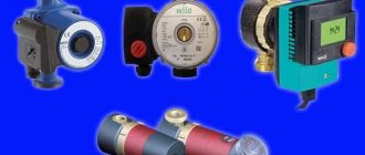
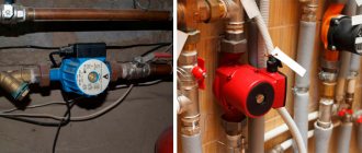
The pump is installed so that its shaft is in a horizontal position, otherwise the formation of air pockets cannot be avoided. They mount it on American ones so that, if necessary, it can be easily removed
In the case when the pump is selected based on an existing boiler, the formula is used: Q=N/(t2-t1), where N is the power of the heating unit in W, t2 and t1 are the temperature of the coolant at the outlet of the boiler and at the return, respectively.
How to calculate an expansion tank?
The calculation comes down to determining the amount by which the volume of the coolant will increase during its heating from the average room temperature of + 20 degrees C to the operating temperature - from 50 to 80 degrees. These calculations are not easy, but there is another way to solve the problem: professionals advise choosing a tank with a volume equal to 1/10 of the total amount of liquid in the system.
The expansion tank is a very important element of the system. The excess coolant it takes in during its expansion saves the line and taps from bursting
You can find out this data from the equipment passports, which indicate the capacity of the boiler water jacket and 1 radiator section. Then the cross-sectional area of pipes of different diameters is calculated and multiplied by the corresponding length.
The results are summed up, data from passports are added to them and 10% is taken from the total. If the entire system holds 200 liters of coolant, then an expansion tank with a volume of 20 liters is needed.
Image gallery
Photo from
A simplified version of tank selection
Membraneless expansion tanks
Expansion tanks with membrane
Expansion tanks for large systems
Types of double-circuit heating systems
Since there are many two-pipe heating systems in use, each of which has its own characteristics, it is worth understanding the basic circuits.
Horizontal and vertical
The heating design is selected based on the number of floors in the building.
The type of layout is determined based on the method of installation of the double-circuit heating system.
A vertical scheme is better suited for structures with several floors, a horizontal one - for one-story buildings of a huge area.
The installation of the first involves a number of separate risers and batteries. The other has one or two risers, as well as several heating sources located on the same level.
Bottom and top wiring
An important distinctive feature is the location of the tank and the heating unit. In the case of upper wiring, they are placed under the roof of the structure, in the case of lower wiring, in the basement.
Systems with associated and counter movement of water
Scheme with associated and dead-end movement of the coolant.
In the first, the heated liquid in both circuits has the same direction of movement. In others, cold water flows out from the opposite direction when compared to the direction of movement from the boiler. In such a design there is an end radiator where the 2 most distant points are connected.
With natural and forced circulation
The movement of the coolant occurs under the influence of temperature differences in the contours of structures with natural circulation. In this case, the water heats up slowly, but there is no need to install a pump. In systems with forced circulation, a pump is installed on one circuit, the operation of which sets the coolant in motion. Thanks to this popular scheme, heat is distributed evenly throughout the building.
Operating principle of closed type heating
What does a closed heating circuit look like? The main design feature, which determines the name of such a system, is its tightness.
A closed-type heating system, the diagram of which includes elements, some of which are used in other types of heating, looks like this:
- boiler;
- air valve;
- thermostat;
- heating appliances;
- expansion tank;
- balancing valve;
- ball valve;
- pump and filter;
- pressure gauge;
- safety valve.
This is what closed-type heating looks like, the diagram and principle of operation of which is quite simple: the liquid circulating in the system is heated in the boiler and enters the pipeline. When expanding, excess liquid enters the tank, and when the temperature drops, it returns back, which makes it possible to maintain the internal pressure in the system at a given level (pro
Beam system with collectors
Radiant heating system using a collector.
This is one of the most modern schemes, which involves laying an individual line to each heating device. To do this, collectors are installed in the system - one collector is the supply, and the other is the return. Separate straight pipes diverge from the collectors to the batteries. This scheme allows for flexible adjustment of heating system parameters. It also makes it possible to connect heated floors to the system.
The radial wiring diagram is actively used in modern homes. The supply and return pipes here can be laid in any way - most often they go in the floors, after which they are suitable for one or another heating device. To regulate the temperature and turn on/off heating appliances, small distribution cabinets are installed in the house.
According to heating engineers, this scheme is ideal, since each heating device operates from its own mains and is almost independent of other heating devices.
Advantages and disadvantages of beam systems
There are many positive qualities:
- the ability to completely hide all pipes in the walls and floors;
- convenient system setup;
- possibility of creating remote separate adjustment;
- minimum number of connections - they are grouped in distribution cabinets;
- it is convenient to repair individual elements without interrupting the operation of the entire system;
- almost perfect heat distribution.
When installing a radiant heating system, all pipes are hidden in the floor, and the collectors are hidden in a special cabinet.
There are also a couple of disadvantages:
- high cost of the system - this includes the costs of equipment and installation costs;
- difficulty in implementing the scheme in an already built house - usually this scheme is laid out at the stage of creating a home ownership project.
If you still have to put up with the first drawback, then there is no escape from the second.
Features of installation of radiant heating systems
At the project creation stage, niches are provided for laying heating pipes, and installation points for distribution cabinets are indicated. At a certain stage of construction, pipes are laid, cabinets with collectors are installed, heating devices and boilers are installed, a test run of the system is carried out and it is checked for leaks. It is best to entrust all this work to professionals, since this scheme is the most complex.
Despite its complexity, a radiant heating system with collectors is one of the most convenient and efficient. It is used not only in private homes, but also in other buildings, for example, in offices.
Design and operational features of the systems - notes for home craftsmen
The expansion tank may be installed next to the circulation pump. Moreover, both of these elements of the system can be placed with the heating boiler in the same room. This means that you will achieve a reduction in the footage of the main line and save on the purchase of additional pipes. And the need to install fewer pipe products will please any home craftsman who is accustomed to doing home repairs with his own hands.
A closed heating system is equally effective for a private house with a small area and for spacious cottages. It can be installed even in very spacious industrial and special facilities. This distinguishes closed systems from open ones, which function effectively only in buildings with a small area.
Closed heating system in a cottage
Note! In most cases, the circulation unit and expansion tank are placed on the return line, thereby increasing the time of its use (the cooled coolant causes less operational damage to the pump).
But there are also devices that can be placed on the supply pipe. Such pumps are treated with a special lubricant, which perfectly protects them from the negative effects of hot water.
How to choose equipment
One of the important points is the selection of a heat source based on power and type of energy carrier used:
- on natural or liquefied gas;
- on solid fuel - wood, coal, pellets;
- on electricity;
- on liquid fuel - diesel fuel, waste oil.
Reference. If necessary, you can choose a combined multi-fuel installation, for example, wood and electricity or gas + diesel fuel.
The power of the boiler installation is calculated in the standard way: the heated area of the home is multiplied by 0.1 to convert to kilowatts and by a safety factor of 1.3. That is, for a house of 100 m² you need a heat source with a power of 100 x 0.1 x 1.3 = 13 kW.
For a closed heating system, it does not matter which heat generator you buy, so we will not consider this issue in detail. But you will make your task much easier if you purchase a wall-mounted gas boiler equipped with its own circulation pump and expansion tank, as shown in the photo. For a small house, all that remains is to select pipes and heating devices, which will be discussed further.
Types of pipes
The heating network of a private house can be installed from the following pipes:
- PPR (polypropylene);
- cross-linked polyethylene – PEX, PE-RT;
- metal-plastic;
- metal options: copper, steel and corrugated stainless steel.
For self-installation at low financial costs, it is better to take polymer pipes. To assemble crimp connections from metal-plastic and polyethylene, you do not need special tools, but polypropylene will have to be soldered (a welding machine is rented). Of course, PPR material has no equal in cost, but for reasons of reliability and durability, we recommend using PEX pipelines made of cross-linked polyethylene.
Copper and corrugated stainless steel can also be mounted on compression fittings, but the first has a high price, and the second has significant hydraulic resistance. As for ferrous metal, it is inconvenient in all respects - welding installation and susceptibility to corrosion relegate it to last place. More details about the choice of pipes are described in the next video:
Which radiators are better
The following types of heating devices are currently offered in the retail chain:
- steel panels;
- made from an alloy of aluminum and silicon (silumin);
- the same, but with a frame made of steel pipes, name - bimetallic;
- cast iron batteries are analogues of the Soviet “accordion” MC 140 and retro-style models.
Note. The last 3 types of radiators are assembled from the required number of sections for heat transfer.
Steel panel radiator
From the point of view of economy, it is more profitable to buy steel batteries, which have an affordable price. Aluminum appliances are more expensive, but give off heat more intensely. These 2 varieties are most in demand for closed heating systems in private houses.
Aluminum heating device
Bimetallic radiators are designed for heating networks with low-quality coolant supplied with pressure drops, which is typical for centralized heating supply of apartment buildings. It makes no sense to buy these expensive products for a country house with autonomous heating.
Cast iron accordions are much inferior to other batteries in appearance and weight. But due to their low price, they are used in industrial buildings and outbuildings. At the same time, vintage cast iron radiators have an impeccable design, but are too expensive in price.
To select a heating device based on power, make a simple calculation: divide the heat transfer indicated in the passport by 1.5. This way you will find out the real power of the radiator, because the documentation reflects characteristics for certain operating conditions that do not coincide with reality.
Advice. Don’t forget to purchase radiator fittings - a ball valve for the supply and a balancing valve for the return. If you decide to install energy-saving thermostats with presetting on batteries, then a regular shut-off valve should be installed at the outlet of the device.
Pump and expansion tank
In closed heating systems of private homes, 3 types of household circulation pumps are usually used, developing a pressure of 4, 6 and 8 m of water column (this is a pressure of 0.4, 0.6 and 0.8 bar, respectively). We suggest that you do not delve into complex hydraulic calculations, but select a pumping unit based on the following characteristics:
- For one- and two-story buildings with an area of up to 200 m², a pressure of 4 m is sufficient.
- A cottage with an area of 200-300 m² will need a pump with a pressure of 0.6 Bar (6 m).
- Circulation in the network of a three-story mansion of 400-500 m² will be provided by a unit with a pressure of 8 m of water column.
Reference. The power of the pump must be judged by its markings. For example, a Grundfos 25-40 brand product has a connection diameter of 25 mm and develops a pressure of 0.4 Bar.
To select the size of the expansion tank, you should calculate the volume of water in the entire closed heating system along with the boiler tank. Considering the fact that when heated from 10 to 90 °C, water expands by approximately 5%, the capacity of the tank should be 1/10 of the total amount of coolant.
