What are the benefits of pump heating systems?
30 years ago, so-called steam heating was common in private homes, where the coolant circulated through pipes and radiators by gravity, and the heat source was a gas boiler or wood stove. Pumps for pumping water were used in district heating networks. When compact circulation pumps for heating appeared, they migrated to private housing construction, as they provided the following advantages:
- The speed of coolant movement has increased. The heat generated by the boiler has become faster delivered to the radiators and transferred to the premises.
- Accordingly, the process of heating the house has accelerated significantly.
- The higher the flow rate, the greater the throughput of the pipe. This means that the same amount of heat can be delivered to rooms through lines of smaller diameter. Simply put, the pipelines have become half the size thanks to the forced circulation of water from the pump, which is cheaper and more practical.
- Highways can now be laid with a minimum slope and water heating circuits can be made as complex and extensive as desired. The main thing is the correct selection of the pumping unit in terms of power and pressure created.
- The household circulation pump for heating has made it possible to organize underfloor heating and more efficient closed systems operating under pressure.
- It was possible to remove from view the ubiquitous pipes that run through the rooms and do not always harmonize with the interior. Increasingly, heating communications are laid in walls, under floor coverings and behind suspended (suspended) ceilings.
Note. A minimum slope of 2-3 mm per 1 m of pipeline is needed to empty the network in case of repair or maintenance. Previously, it was made at least 5 mm / 1 m.p.
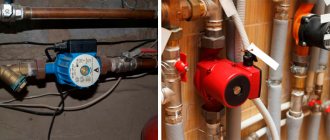
Pumping systems also have disadvantages. This is a dependence on electricity and its consumption by the pumping unit during the heating season. Therefore, if there are frequent power outages, the circulation pump must be installed together with an uninterruptible power supply unit or connected to an electric generator. The second drawback is not critical; if you select the power of the device correctly, then the electricity consumption will be acceptable.
Leading manufacturers of heating equipment, such as Grundfos or Wilo, have developed new models of units that can save energy. For example, if you buy and install an Alpfa2 circulation pump from the Grundfos brand, it will automatically change its performance depending on the needs of the heating system. True, its price starts from 120 USD. e.
New generation circulation units from Grundfos – models Alpfa2 and Alpfa2L
Where to install the pump - supply or return
Despite the abundance of information on the Internet, it is quite difficult for the user to understand how to correctly install a heating pump in order to ensure forced circulation of water in the system of their own home. The reason is the inconsistency of this information, which causes constant debate on thematic forums. Most of the so-called specialists claim that the unit is installed only on the return pipeline, citing the following conclusions:
- the coolant temperature in the supply is much higher than in the return, so the pump will not last long;
- The density of hot water in the supply line is less, so it is more difficult to pump;
- The static pressure in the return line is higher, which makes the pump easier to operate.
Interesting fact. Sometimes a person accidentally ends up in a boiler room that provides central heating for apartments, and sees the units there embedded in the return line. After this, he considers this solution to be the only correct one, although he does not know that in other boiler houses centrifugal pumps can also be installed on the supply pipe.
We respond to the above statements point by point:
- Household circulation pumps are designed for a maximum coolant temperature of 110 °C. In a home heating network it rarely rises above 70 degrees, and the boiler will not heat the water more than 90 °C.
- The density of water at 50 degrees is 988 kg/m³, and at 70 °C – 977.8 kg/m³. For a unit that develops a pressure of 4-6 m of water column and is capable of pumping about a ton of coolant in 1 hour, the difference in the density of the transported medium is 10 kg/m³ (the volume of a ten-liter canister) is simply negligible.
- In practice, the difference in static pressure of the coolant in the supply and return lines is equally insignificant.
Hence the simple conclusion: circulation pumps for heating can be installed both in the return and supply pipelines of the heating system of a private house. This factor will not in any way affect the performance of the unit or the heating efficiency of the building.
Boiler room made by our expert Vladimir Sukhorukov. There is convenient access to all equipment, including pumps.
The exception is cheap solid fuel direct combustion boilers that are not equipped with automation. When overheated, the coolant in them boils, since burning wood cannot be extinguished at once. If the circulation pump is installed on the supply side, then the resulting steam mixed with water enters the housing with the impeller. The further process looks like this:
- The impeller of the pumping device is not designed to move gases. Therefore, the performance of the device decreases sharply, and the flow rate of the coolant drops.
- Less cooling water enters the boiler tank, causing overheating to increase and even more steam to be produced.
- An increase in the amount of steam and its entry into the impeller leads to a complete stop of the coolant movement in the system. An emergency situation occurs and, as a result of an increase in pressure, a safety valve is activated, releasing steam directly into the boiler room.
- If no measures are taken to extinguish the firewood, the valve cannot cope with the pressure release and an explosion occurs with the destruction of the boiler shell.
For reference. In cheap heat generators made of thin metal, the response threshold of the safety valve is 2 Bar. In higher quality TT boilers, this threshold is set at 3 Bar.
Practice shows that no more than 5 minutes pass from the start of the overheating process to the valve activation. If you install a circulation pump on the return pipe, then steam will not enter it and the time period before an accident will increase to 20 minutes. That is, installing the unit on the return line will not prevent an explosion, but will delay it, which will give more time to fix the problem. Hence the recommendation: it is better to install pumps for boilers running on wood and coal on the return pipeline.
For well-automated pellet heaters, the installation location does not matter. You will learn more information on the topic from our expert’s video:
Installation Basics
The inclusion of autonomous heating in the circuit and the presence of central heating there is regulated by SP 60.13330. According to this act, a heating system with forced circulation is considered priority (not with natural circulation, although this is also possible).
The installation process briefly consists of securing the assembled pump unit (with filters, taps) with union nuts to a pre-cut pipe in a certain place.
Peculiarities
For wet pumps:
- placed so that the position of the shaft is clearly horizontal (not necessary for dry options) - this will eliminate airing, spare parts will not break because of it;
- the filter is a standard mud trap; it is mounted with its branch downwards along the flow of water to reduce resistance and facilitate maintenance.
For older products, the factory can indicate the installation location; once upon a time only the return line was considered such, but modern pumps can be installed anywhere (on the supply side too).
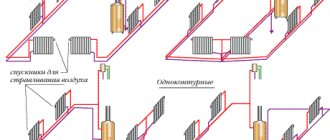
Autonomous heating pump installation diagrams
Let's look at the basic diagrams of how to install a pump and embed it onto a pipe.
They put it on return/feed, there is no difference. You can cut it directly onto the main pipe or make a bypass (outlet) and place it on it. The last method is the best, it makes it possible to more conveniently dismantle/install the device for maintenance; when replacing, it is usually so familiar that it is assumed by default.
There are several options for the installation location; there is also a diagram for several pumps (manifold connection).
Let's consider the traditional option with installation on a bypass.
For modern models, the location - return or supply - is not significant. They choose at their own discretion, as is more convenient for the user.
But, undoubtedly, in all cases the best option is to tap into the bypass in these places.
Some specialists remain adherents of the old traditional rule, according to which the return is the best section for installation. Through this segment, the liquid that has given off heat returns to the boiler. A less warm, cooled resource does not have such an aggressive effect on the device. The described opinion has completely lost its relevance for modern models designed for high temperatures, however, we indicate it for a full disclosure of the topic. It is important to read the instructions, since for older products the manufacturer may recommend a return line.
If the device is cut into the supply segment, then not directly close to the boiler, but after the safety group.
Option for solid fuel boiler. NC is not installed on the supply section due to the risk of explosion, since with the specified type of unit the heating does not stop quickly. This is a boiler with great inertia. Even if you turn it off, the intensity of fuel combustion may increase for some time, there is a risk of water boiling, the liquid expands, the pressure increases, creating a steam bomb. Boiling water is mixed with steam, gets inside the device, reduces productivity, and the cooled resource in the circuit does not have time to refill the boiler in the required volume - the device becomes hot, and there is a high probability of an explosion.
When a cooled resource is launched into a heated TD boiler, condensation forms. To eliminate this phenomenon, the liquid is first heated on the small circuit to +55° C, and then the thermal valve slowly switches to the main circuit. Cool masses are mixed with already heated ones, the sharp difference in temperature is leveled out.
Pump in a natural circulation system
One of the options for autonomous heating is an open line, where the expansion tank is mounted at the highest point. The inclusion of a circulation pump in such a scheme will increase the performance and versatility of the equipment.
The natural circulation is always somewhat limited and unstable, so if you need an increased quality of heating, you can use a pump, and when weak heating is enough or in case of power outages, you can use gravity.
To switch from a forced circulation to a natural one, a particularly important installation is to install the heating pump on the bypass. When the pump is activated, the gravity pipe is closed with a tap. Let us add that installation on bypass is always recommended for all circuits.
Harness
First you need to decide how many superchargers there will be. For one simple line, one device is enough.
When two units are required:
- for a system with complex or multiple circuits;
- if “warm floor” is combined;
- an indirect heating boiler is used;
- two boilers are used, for example, TD and electric (a pump for each).
What is required for installation
What parts need to be prepared for strapping:
- Ball Valves. Mounted together with the pump. They are needed to cut off the flow of water during emergencies and repairs. Placed at the entrance and exit;
- thermostat for the pump (not mandatory, but a desirable element);
- check valve - brass, cast iron - for movement in one given direction. Placed after the pump in the direction of flow;
- a regular dirt filter (for the roughest cleaning). Devices for fine filtration are not installed on heating; if you need clean water, and this quality is always recommended, and especially for “wet” pumps, then it is cleaned before filling;
- air bleed valve to remove air pockets. The unit can be activated automatically, there are also manual products, and it may already be integrated into the device;
- American nuts (often included with pumps);
- bends - sections of pipes with threads at both ends for fitting, connecting pipeline segments when they cannot be rotated;
- tools: open-end wrenches, adjustable wrenches;
- pliers;
- tow, fum tape, sealant (Unipak).
If you need to install a heating pump with assembling the system and inserting it from scratch, then the procedure is not always accessible for you to do it yourself, since you will need to make a bypass, cut the pipe, prepare its ends, which will require welding, a grinder, dies for cutting threads for caps pump lead nuts, for American women.
American women are often included. Taps, adapters, bends (for connecting pipe sections) must be prepared. There should be no difficulties in selecting diameters: they are standard, usually 25, 32 mm.
Installation diagrams in various types of systems
To begin with, let’s clarify the place where to install the flow pump, which circulates water through the boiler and forcibly directs it to the radiators of the heating system. According to our expert Vladimir Sukhorukov, whose experience is trustworthy, the installation location must be chosen in such a way that the unit is convenient to maintain. On the supply side it should be located after the safety group and shut-off valves, as shown in the installation diagram:
In order for the unit to be removed and serviced, shut-off valves must be installed on the sides
On the return line, the pump must be placed directly in front of the heat generator, and in tandem with a filter - a mud trap, so that you do not have to buy and install extra taps. The wiring diagram for the pumping unit looks like this:
When installing on the return line, it is better to place the mud collector in front of the pump unit
Recommendation. A circulation pump can be installed in this way in both a closed and an open heating system, there is not much difference. The statement also applies to the collector system, where the coolant moves to the radiators through separate connections connected to the distribution comb.
A separate issue is an open heating system with a circulation pump, capable of operating in 2 modes - forced and gravity. The latter is useful for homes where power outages often occur, and the owners’ income does not allow them to buy an uninterruptible power supply unit or a generator. Then the device with shut-off valves must be installed on the bypass, and a tap must be inserted into a straight line, as shown in the diagram:
This scheme can operate in forced and gravity mode
Important point. On sale there are ready-made bypass units with a pump, where instead of a tap on the flow there is a check valve. Such a solution cannot be called correct, since a spring-type check valve creates a resistance of the order of 0.08-0.1 Bar, which is too much for a gravity heating system. Instead, you can use a petal valve, but it must be installed only in a horizontal position.
Finally, we will explain how to install and connect a circulation pump to a boiler that burns solid fuel. As mentioned above, it is better to place the unit on the line coming from the heating system to the heat generator, as shown in the diagram:
As you can see, the piping uses a pump connection to the boiler circulation circuit with a bypass and a three-way mixing valve. The important role of these piping elements is described in detail in the manual on connecting solid fuel boilers.
Is it possible to install the pump yourself?
The simple design of the supercharger makes it easy to install. A technician with even minimal plumbing skills can handle its installation. The main difficulty is connecting it to the metal line. In this case, you will need welding equipment and experience working with it.
To connect, in addition to the pump itself, you will need connecting fittings for inserting the pump, shut-off valves, a strainer, winding and plumbing paste. Installation sequence:
- Drain the water from the system (if the connection is made into an existing network).
- A bypass is installed at the installation site.
- Screw on the shut-off valves, filter and mounting flanges.
- A tap or check valve is inserted into the main line between the bypass line taps.
- Install the pump, fill the system with water and check it for leaks.
Having studied all the nuances of installing the pump unit, you can choose the most suitable connection scheme. After developing the project, they begin independent installation or invite specialists to carry out repair work.
Installation rules
The design of a household circulation pump from any manufacturer provides for its fastening to pipelines or shut-off valves using union nuts (American). This allows it to be quickly dismantled if necessary, for example, for replacement or repair. When installing the pump unit, follow these recommendations:
- Place the device on any sections of pipelines - horizontal, vertical or inclined, but with one condition: the rotor axis must be in a horizontal position. That is, installation “head down” or up is unacceptable.
- Please note that the plastic box with electrical contacts is located on top of the case, otherwise it will be flooded with water in the event of an accident. Yes, and servicing the product will not be easy. This is easy to achieve: unscrew the screws securing the casing and turn it to the desired angle.
- Remember to follow the flow direction indicated by the arrow on the housing.
- So that the product can be removed without emptying the system, install shut-off valves before and after it, as shown in the diagrams in the previous section.
A visual aid showing what position the pump unit should be in
Advice. It so happened that the load from the weight of the circulation unit will fall on 1 or 2 ball valves (depending on the orientation of the area in space). Hence the recommendation: do not save money and buy high-quality shut-off valves, whose body will not crack over time from mechanical stress.
About installing additional units
As a rule, in a closed or open radiator heating system, where the heat source is a single boiler, it is enough to install one circulation pump. In more complex schemes, additional units are used for pumping water (there may be 2 or more of them). They are placed in the following cases:
- when more than one boiler installation is used to heat a private house;
- if a buffer tank is involved in the piping scheme;
- the heating system has several branches serving various consumers - radiators, heated floors and an indirect heating boiler;
- the same, using a hydraulic separator (hydraulic arrow);
- for organizing water circulation in underfloor heating circuits.
Correct wiring of several boilers operating on different types of fuel requires that each of them have its own pumping unit, as shown in the diagram for the joint connection of an electric and TT boiler. How it functions is described in our other article.
Connecting an electric and TT boiler with two pumping devices
In a circuit with a buffer tank, it is necessary to install an additional pump, because it involves at least 2 circulation circuits - boiler and heating.
The buffer tank divides the system into 2 circuits, although in practice there are more of them
A separate story is a complex heating scheme with several branches, implemented in large cottages with 2-4 floors. Here, from 3 to 8 pumping devices can be used (sometimes more), supplying coolant floor by floor and to different heating devices. An example of such a circuit is shown below.
Finally, a second circulation pump is installed when heating the house with water-heated floors. Together with the mixing unit, it performs the task of preparing coolant with a temperature of 35-45 ° C. The operating principle of the circuit presented below is clearly described in a separate material.
This pumping unit forces coolant to circulate through the heating circuits of underfloor heating.
Reminder. Sometimes pumping devices do not need to be installed for heating at all. The fact is that most electric and gas wall-mounted heat generators are equipped with their own pumping units built inside the housing.
Features of forced circulation
The forced heating system is more reliable and practical, can be adjusted if necessary
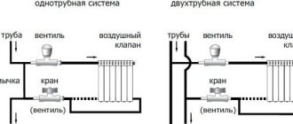
Water or other coolant moves through the heating circuit due to circulation. It comes in two types – natural and forced. In the first case, no additional equipment is required; the liquid itself moves through the system due to a properly designed circuit. In the second case, the coolant moves under the action of a circulation pump.
Natural circulation of water along the circuit has an important advantage - ease of installation and a minimum amount of equipment. But it is less effective, since many different nuances need to be taken into account. If the inclination angles and pipe diameters are incorrectly calculated, the system will not work.
Forced circulation is more reliable and of higher quality. It has the following advantages:
- The diameter of the pipes is small compared to the natural circulation system. As a result, the cost will be lower. In addition, a pipeline with a small cross-section does not spoil the appearance of the room.
- Possibility of hidden connection of radiators.
- No complex calculation of pipe angles is required.
- Versatility and efficiency.
Stopping the pump in the absence of electricity can lead to an explosion of the solid fuel boiler
The disadvantages include:
- Expensiveness of the pump. It also requires electricity to operate, which will incur financial costs.
- Risk of equipment failure.
- The system will not be operational if the power goes out. It is necessary to provide for the possibility of autonomous power supply of the pump.
Despite its disadvantages, forced circulation is preferable for use in homes.
Installing a circulation pump in a heating system solves several problems:
- uniform heating of heating devices;
- expansion of the heating system circuit;
- eliminating the problem of air jams.
Can be installed into a finished heating system by inserting it.
Connecting the circulation pump to the electrical network
There are several ways to connect power to the device:
- through a conventional differential machine;
- with thermostat control;
- connection to the network together with an uninterruptible power supply unit (UPS);
- powering the unit from the boiler automation.
Warning. Often, homeowners simply plug the pump into a regular outlet, connecting the wires to a purchased plug. We cannot recommend this approach, because connection without grounding and a safety device is dangerous. If there is a problem with the device or if it is filled with water, you risk receiving an electric shock.
Typical connection diagram with a differential circuit breaker
The first connection diagram is quite simple and any user can assemble it with his own hands. You will need an 8 A differential circuit breaker, wires and contacts. Connect to grounding both in this circuit and in all others.
To automatically stop the movement of the coolant when cooling to a certain temperature, an electrical circuit is used to connect a circulation pump with a thermostat. The latter is attached to the supply pipeline and breaks the power supply circuit when the water temperature drops below a set value.
Connecting a phase wire to the pump through an overhead thermostat
Attention! To ensure that the thermostat does not lie and turns off the circulation in time, it must be attached to a metal section of the line. Polymers do not transfer heat well, so when mounted on a plastic pipe, the device will not work correctly.
There are no difficulties in connecting the power supply through a UPS, for which the latter has special connectors. The heat generator itself should also be connected to them if it needs electricity. But connecting the pump to the boiler control panel or to its automation is a more complicated procedure. It is advisable to have knowledge and skills in the field of electrical engineering.
The boiler is also connected to the uninterruptible unit if it needs electricity
At what speed should the pump in the heating system operate?
The purpose of forced circulation is to effectively heat the house through the reliable delivery of heat to all consumers of the system, right up to the furthest radiator. To do this, the pumping unit must develop the required pressure (otherwise known as pressure), which is ideally calculated by design engineers based on the hydraulic resistance of the pipeline network.
Most household pumps have from 3 to 7 rotor speeds, due to which the performance and pressure generated can be increased or decreased. In order not to torment you with hydraulic calculations, we offer the following method for selecting the optimal speed:
- Find a laser surface thermometer (pyrometer). Put the heating system into operating mode.
- Measure the surface temperature of the pipe at the inlet and outlet of the boiler.
- If the temperature difference is more than 20 °C, increase the rotor speed. After 30 minutes, repeat the measurement.
- When the temperature difference is less than 10 °C, the water flow rate must be reduced. The goal is to achieve a delta between supply and return of about 15 °C.
The minimum number of rotor speeds is 3, but sometimes 7 or more
Advice. Do not switch the pump to a different circulation speed “on the fly”. Disconnect it from the network, move the regulator to a different position, and then put it back into operation.
You can do without a pyrometer when thermometers are installed on the supply and return lines. If the adjustment limits do not allow you to enter the range of 10-20 °C temperature difference, your system is not working efficiently due to an incorrectly selected circulation pump. Too cold return water increases the load on the boiler and increases fuel consumption. Water that is too hot means that it flows too quickly and does not have time to transfer heat to the heating devices.
The leading European brand Grundfos offers the latest generation Alpfa3 circulation pumps, which can independently select performance depending on the load and thus adapt the work to changing conditions. With their help, you can even balance the heating system, which our expert will tell you about in the next video:
Pump selection
The heating system is connected to water. The pump is usually powered by electricity and should not come into contact with liquid. For this reason, all heating circuit pumps are divided into dry and wet.
Dry type
A dry rotor pump is loud and more difficult to install in a heating system
In the dry scheme there is a division into two sealed compartments. In the first pumping part there is direct contact with water, and in the second electrical part there is power from the network. It is completely isolated from liquids.
The advantages of dry appliances include:
- high power;
- high throughput;
- ensuring optimal pressure in the network.
Dry type products are justified in large industrial buildings. It is better not to install them in apartments due to the following disadvantages:
- big sizes;
- complexity of installation;
- the presence of a shaft that wears out over time and requires repair;
- noisy work.
When purchasing a pump, it is important to choose in advance where it will be installed and calculate the volume of water that it will pump. The best place for installation is a separate room for the heating system.
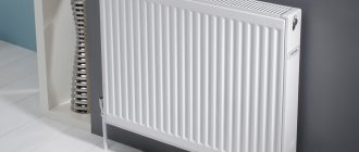
Wet type
For pumps with a wet rotor, you need to install a filter in front of the inlet pipe
This type of equipment is suitable for apartments, one- and two-story private houses. Wet type pump design: a housing with a closed electrical part, which is connected to the pump chamber. It pumps coolant. Sealing is achieved by using a gasket. At the inlet and outlet there are pipes and flanges for connecting pipes.
The electrical part is also divided into two parts. In the center there is a glass that contains all the electrical mechanisms except the starter power circuit. It is hermetically located outside the glass and does not come into contact with water. The glass contains a rotor, on the shaft of which the impeller is attached. To place the glass in the coolant, a valve is used to release air.
The disadvantages of the system include a decrease in efficiency. Pros: low power consumption, simple installation and the ability to install on any section of the pipe. It is important that the glass is in a horizontal position, otherwise, when installed vertically, the mechanism will overheat and quickly fail.
It is important to ensure that plaque particles and dirt do not enter the equipment. To do this, place a cleaning filter in front of the inlet.